Maintenance of channel usage in a wireless communication system

a wireless communication system and channel usage technology, applied in the field of wireless communication systems, can solve the problems of inefficiency of system bandwidth, no data transfer, and disadvantage of prior-art systems

Inactive Publication Date: 2006-02-09
INTEL CORP
View PDF65 Cites 2 Cited by
  • Summary
  • Abstract
  • Description
  • Claims
  • Application Information

AI Technical Summary

Problems solved by technology

Prior-art systems are disadvantageous because the wireless access device maintains a channel on a physical layer when the subscriber terminal needs to maintain an active channel, even if there is no payload data being transferred over the physical channel.
This system is bandwidth inefficient because data transmissions in computer networks are “bursty,” characterized by a short transfer of high-rate data, followed by a relatively long period in which no data are transferred.
This inefficiency reduces the number of subscribers that can be working on a system.

Method used


Image

  • Maintenance of channel usage in a wireless communication system
  • Maintenance of channel usage in a wireless communication system
  • Maintenance of channel usage in a wireless communication system

Examples


Embodiment Construction

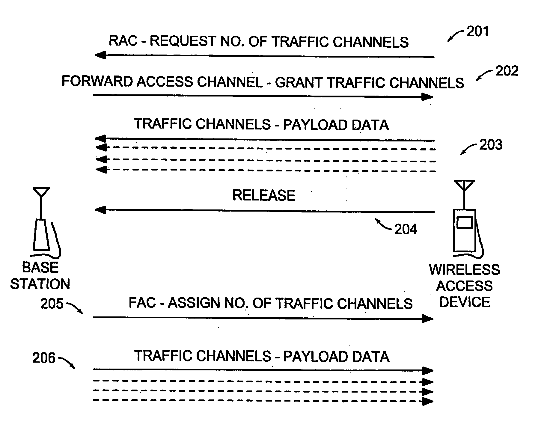
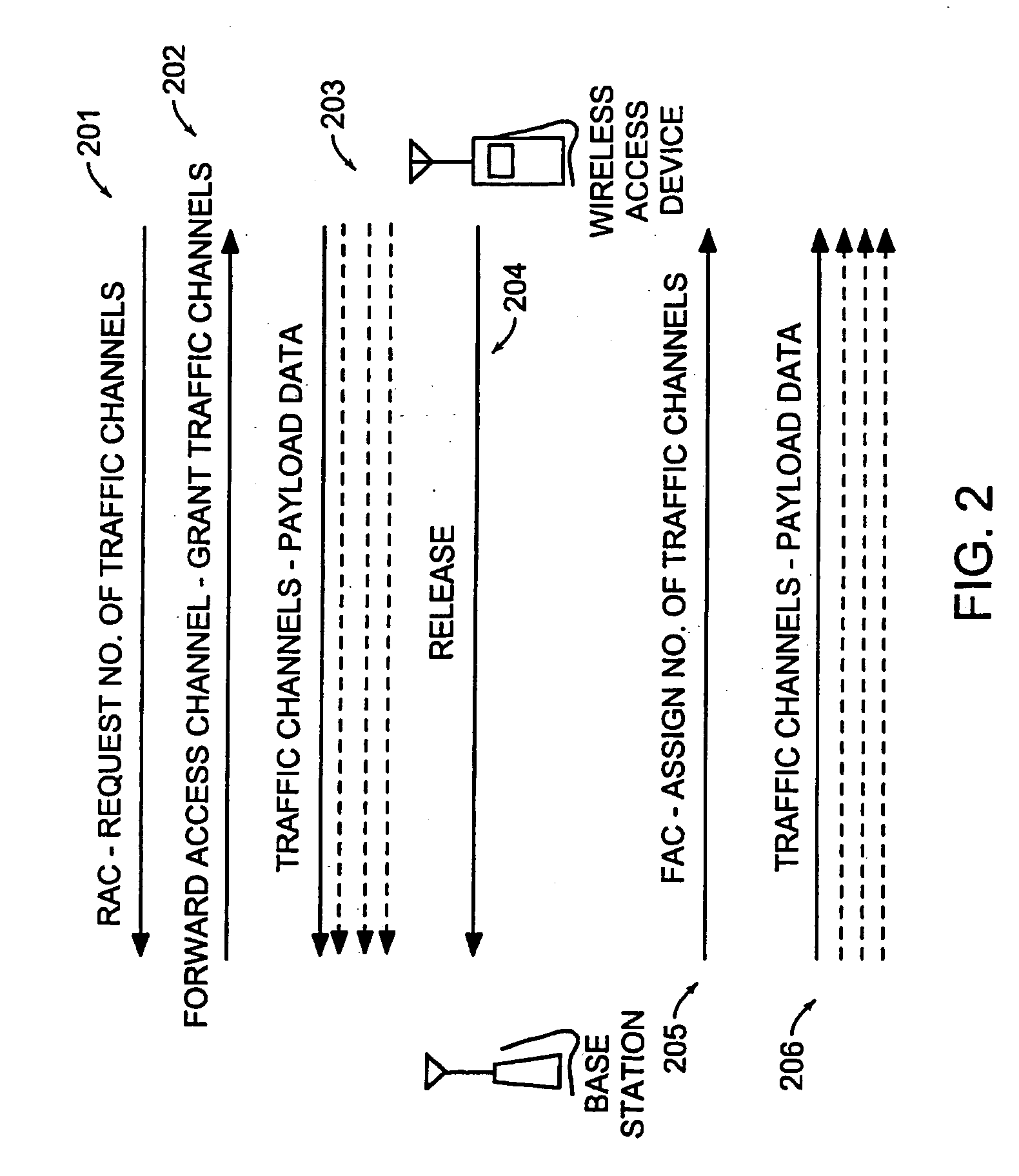
[0012] The present invention relates to a wireless communication system. In particular, the present invention relates to network conmiunicatjon in a wireless environment in which an idle mode is maintained until data is ready for transmission, and then an active mode is entered for transmission.

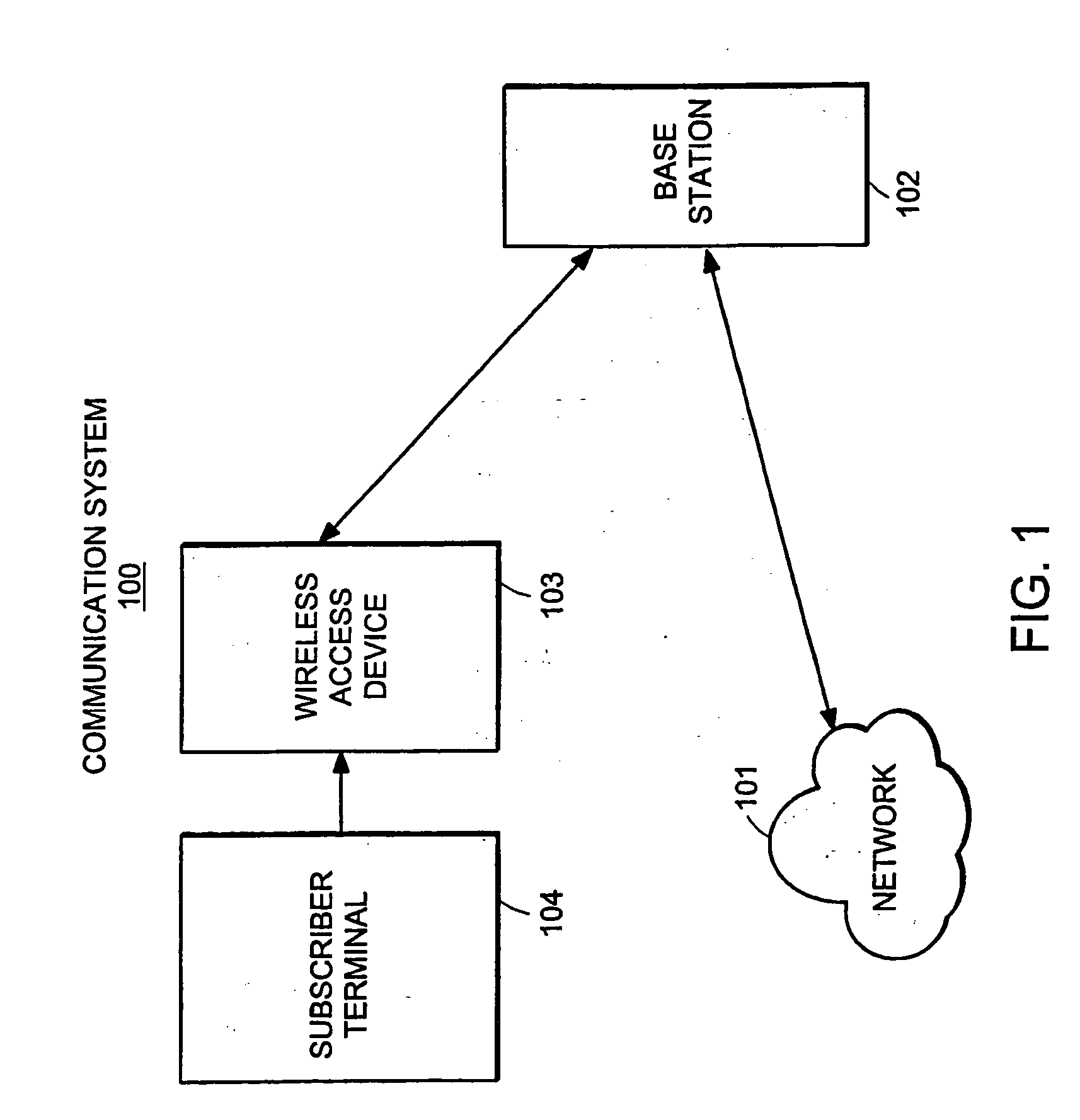
[0013]FIG. 1 is a block diagram illustrating a network-communication system constructed in accordance with an embodiment of the present invention. The communication system 100 can include network 101, base station 102, wireless access device 103, and subscriber terminal 104. Wireless access device 103 is typically a wireless, non-roaming device, although the present invention is not limited to non-roaming devices.

[0014] Wireless access device 103 can receive payload data from subscriber terminal 104, and transmit both payload and other types of data over communication system 100. Wireless access device can communicate with network 101 through a wireless connection with base station 102. Wir...


PUM


Abstract

Data is accessed from a network via a wireless communication link. A determination is made as to whether payload data has been received from a subscriber's terminal. If so, then a request is sent for a first set of traffic channels, and the payload data is transmitted over the first set of traffic channels.

Description

RELATED APPLICATION [0001] This application is a continuation of U.S. application Ser. No. 09 / 288,229, filed Apr. 8, 1999. The entire teachings of the above application are incorporated herein by reference.BACKGROUND OF THE INVENTION [0002] The present invention relates to a wireless communication system. In particular, the present invention relates to systems and methods for providing wireless connections between a wireless access device and a network. [0003] Wireless access for computing networks is known in the art. Typically such systems are implemented by a layered wireless communication system. Layered communication systems are characterized by levels of processing that are performed for transmission and reception of a data signal. For example, a “physical layer” typically refers to processing that is performed to package a signal for radio transmission; it may include error coding, data interleaving digital code modulation, and other conventional processing. The physical laye...

Claims


Application Information

Patent Timeline
Patent Type & Authority Applications(United States)
IPC IPC(8): H04Q7/20H04L12/28H04L12/56H04W72/04H04W76/06H04W84/08
CPCH04W72/0413H04W76/06H04W72/14H04J13/00H04W84/08H04W76/30H04W72/21H04W72/23H04J13/16H04J2013/0096H04L5/0044
Inventor FERGUSON, CHARLES T.GORSUCH, THOMAS
Owner INTEL CORP
Why Eureka
Try Eureka