Receiver and receiving method
a receiver and receiver technology, applied in the field of digital receivers, can solve the problems of decoding video and audio signals that may include noise, the receiver manufacturer cannot improve the processing module, and the receiver cannot correct the error on the receiver side, etc., and achieve the effect of reducing nois
- Summary
- Abstract
- Description
- Claims
- Application Information
AI Technical Summary
Benefits of technology
Problems solved by technology
Method used
Image


Examples
first embodiment
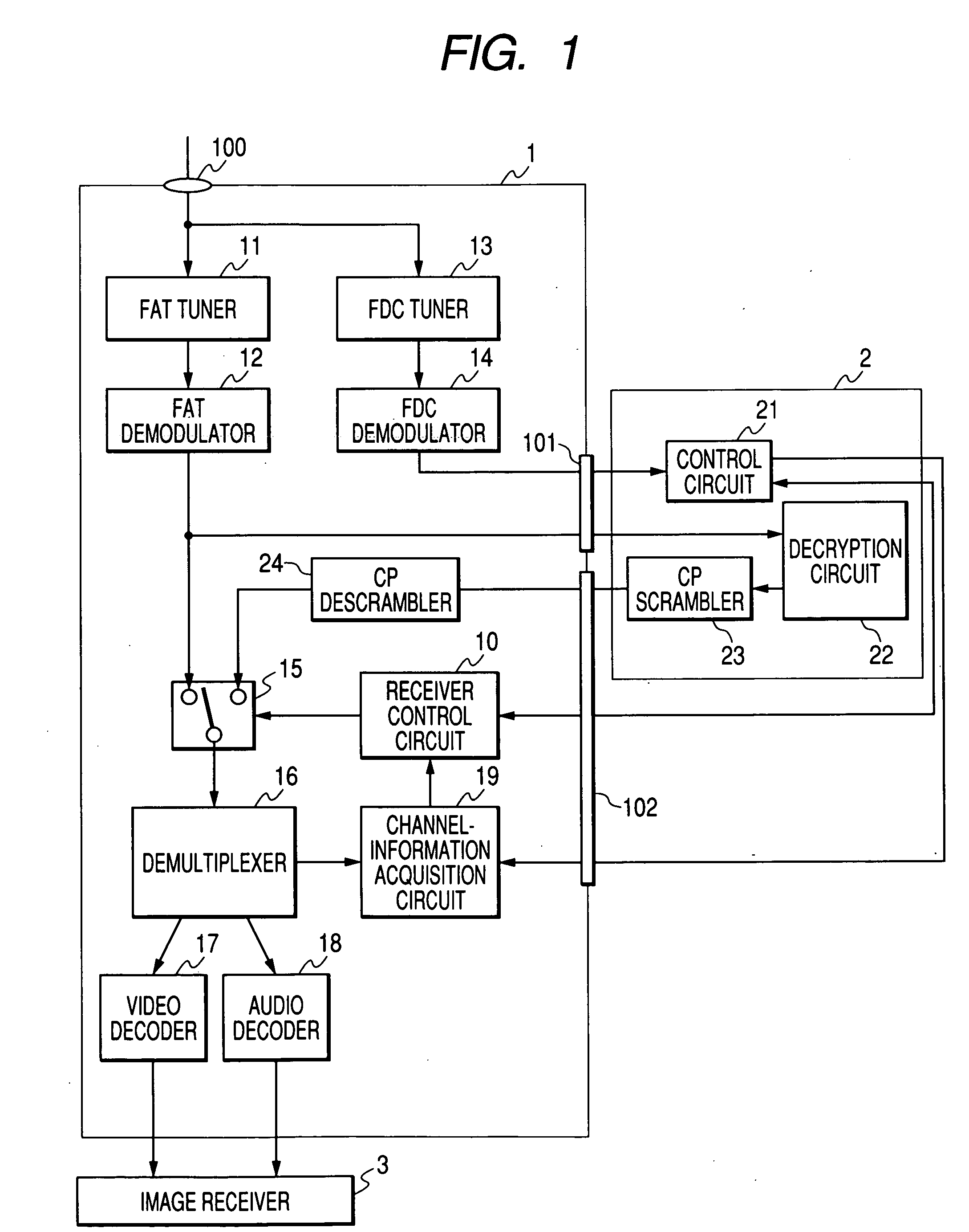
[0034]FIG. 1 is a block diagram schematically illustrating a configuration of a digital-stream control system according to a first embodiment of the present invention. Reference numeral 1 denotes a digital receiver; and reference numeral 2 denotes an external module.
[0035] A high-frequency modulation signal including FAT and FDC is inputted into an input terminal 100, and is then supplied to a FAT tuner 11 and a FDC tuner 13. The FAT tuner 11 selects a station in response to a FAT channel frequency. A FAT demodulator 12 demodulates a selected modulated signal before a digital stream is output. In like manner, the FAT tuner 11 selects a station in response to a FDC channel frequency. The FDC demodulator 14 demodulates a selected modulated signal before FDC data is output. If a FAT channel is CA-scrambled on a transmitting station, the digital stream to be output is scrambled. From the receiver 1, the digital stream is supplied to a decryption circuit 22 of an external processing mod...
second embodiment
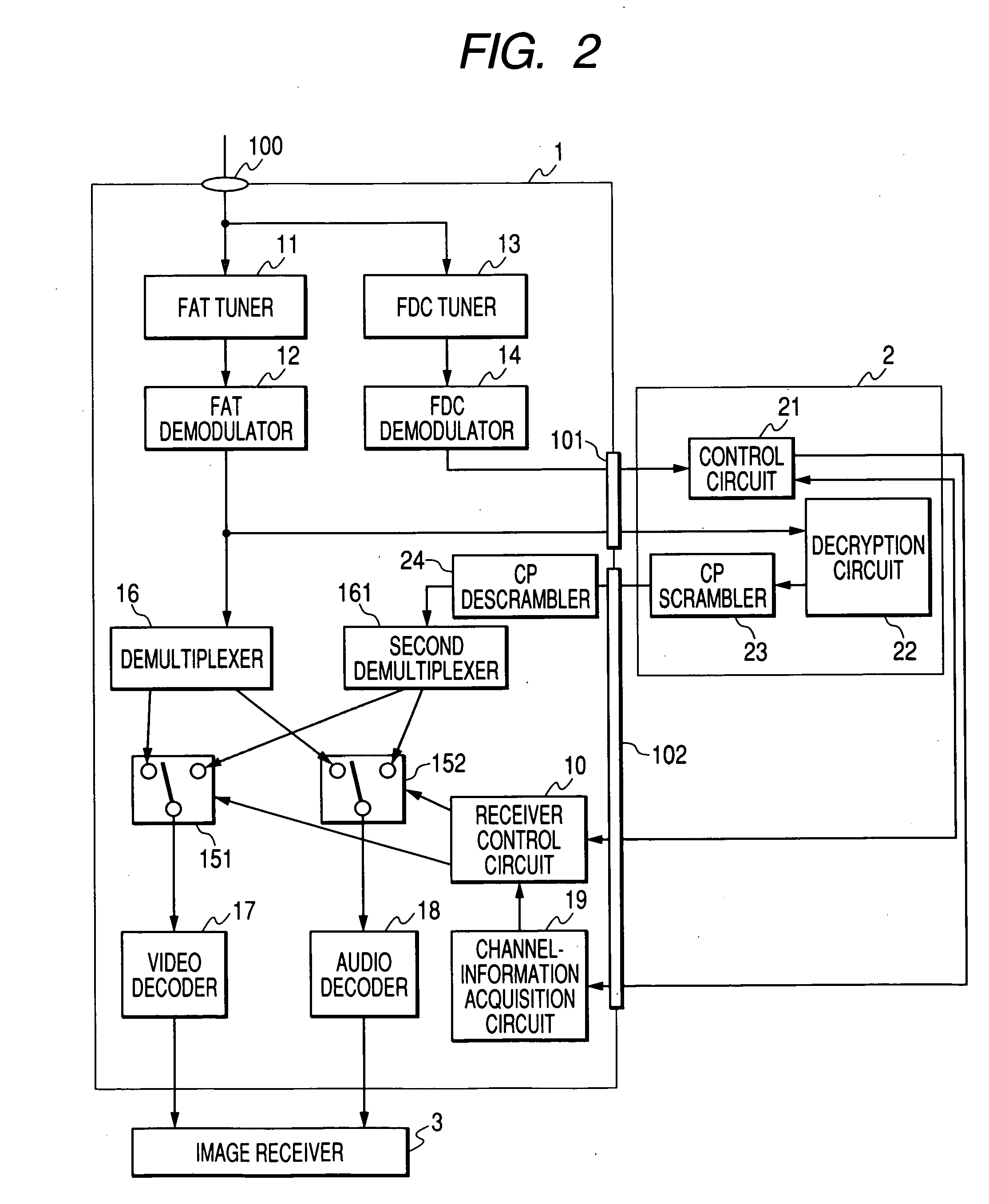
[0042]FIG. 2 is a block diagram schematically illustrating a configuration of a digital-stream control system according to a second embodiment of the present invention. In FIG. 2, the same circuits are designated by reference numerals similar to those in FIG. 1. Reference numeral 161 denotes a second demultiplexer; reference numeral 151 denotes a video-encoded signal switching circuit; and reference numeral 152 denotes an audio-encoded signal switching circuit. A description will be made with reference to drawings as below.
[0043] The FAT tuner 11, the FAT demodulator 12, the FDC tuner 13, the FDC demodulator 14, the processing module 2, and the channel-information acquisition circuit 19 operate in a manner similar to that of the first embodiment. In the second embodiment, what is switched according to whether or not a digital stream is CA-scrambled is not the digital stream, but encoded video and audio signals, into which the digital stream is demultiplexed by a demultiplexer.
[004...
fourth embodiment
[0055] Next, FIG. 4 is a diagram illustrating a configuration of a digital-stream control system according to a fourth embodiment. The digital-stream control systems according to the first, second, and third embodiments may further comprise a second CP scrambler 103, and an external-device connection terminal 104. In this embodiment, the second CP scrambler 103 scrambles video and audio signals that have been demultiplexed by the demultiplexer 16. The use of this scrambling is not limited to receiving. This is scrambling prescribed for transmission. The video and audio signals which have been scrambled are output to external devices through the external-device connection terminal 104. Here, the external devices are, for example, DVHSs and personal computers. The external devices also include personal recording media. Incidentally, in FIG. 4, components excluding the second CP scrambler 103 and the external-device connection terminal 104 are similar to those shown in FIG. 1.
[0056] A...
PUM
 Abstract
Description
Claims
Application Information
 - R&D
- Intellectual Property
- Life Sciences
- Materials
- Tech Scout
- Unparalleled Data Quality
- Higher Quality Content
- 60% Fewer Hallucinations
Browse by: Latest US Patents, China's latest patents, Technical Efficacy Thesaurus, Application Domain, Technology Topic, Popular Technical Reports.
© 2025 PatSnap. All rights reserved.Legal|Privacy policy|Modern Slavery Act Transparency Statement|Sitemap|About US| Contact US: help@patsnap.com