
Two-beam scanning optical apparatus

a scanning optical and beam technology, applied in the direction of instruments, printing, electric discharge tubes, etc., can solve the problems of no more than an emergency measure, no longer being able to replace the print head unit, and no longer being able to meet the requirements of the intended use of the device array, so as to reduce the resolution or the system speed

Inactive Publication Date: 2006-01-26
KONICA MINOLTA BUSINESS TECH INC
View PDF2 Cites 3 Cited by
  • Summary
  • Abstract
  • Description
  • Claims
  • Application Information

AI Technical Summary

Benefits of technology

[0009] Accordingly, it is an object of the present invention to provide a two-beam scanning optical apparatus which, even when one of the two beam generating devices has failed, can continue image formation by using the other normally operating beam generating device, without reducing the resolution or the system speed compared with the case of two-beam image formation.
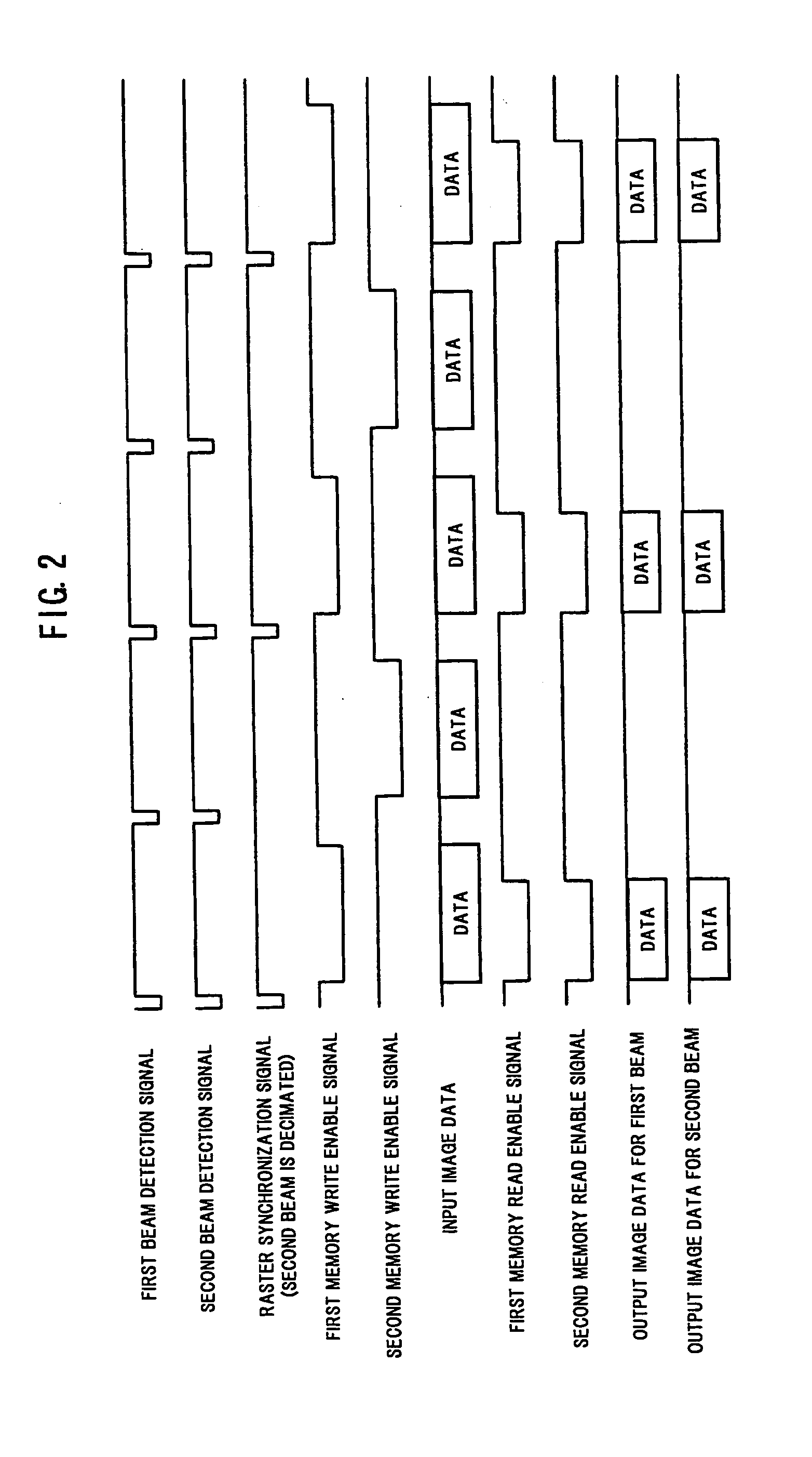
[0013] With the above control operations, even when one of the beam generating devices has failed, image formation can be continued by using the other normally operating beam generating device, without reducing the resolution or the system speed compared with the case of two-beam image formation. Even when driving with one beam, since the image quality does not degrade, nor does the printing throughput drop, there is no need to replace the print head unit, which is thus economical.
[0016] In the two-beam scanning optical apparatus according to the second invention, as in the two-beam scanning optical apparatus according to the first invention, even when one of the beam generating devices has failed, image formation can be continued by using the other normally operating beam generating device, without reducing the resolution or the system speed compared with the case of two-beam image formation. Even when driving with one beam, since the image quality does not degrade, nor does the printing throughput drop, there is no need to replace the print head unit, which is thus economical.

Problems solved by technology

In a two-beam light emitting device array, if one light emitting device fails, the device array can no longer be used for its intended purpose and, as a result, the print head unit (at least a unit containing the scanning optical apparatus) must be replaced.
However, in the case of low speed machines, it would be uneconomical to replace the print head unit because of an emission failure of one beam.
Such a control method, however, provides no more than an emergency measure, since the printing throughput drops by a factor of two, and eventually, replacement of the print head unit would become inevitable.
On the other hand, if a failure (including device deterioration) has occurred in one of the beam generating devices, one-beam image formation is performed using the other normally operating beam generating device.

Method used


Image

  • Two-beam scanning optical apparatus
  • Two-beam scanning optical apparatus
  • Two-beam scanning optical apparatus

Examples


Embodiment Construction

[0026] An embodiment of a two-beam scanning optical apparatus according to the present invention will be described with reference to the accompanying drawings.

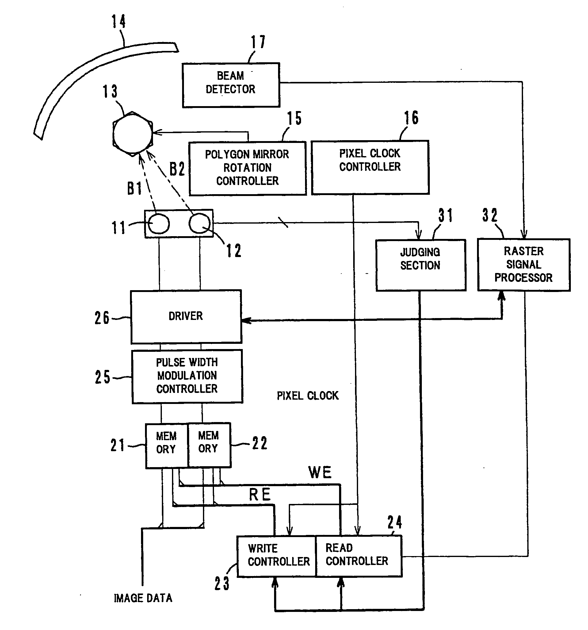
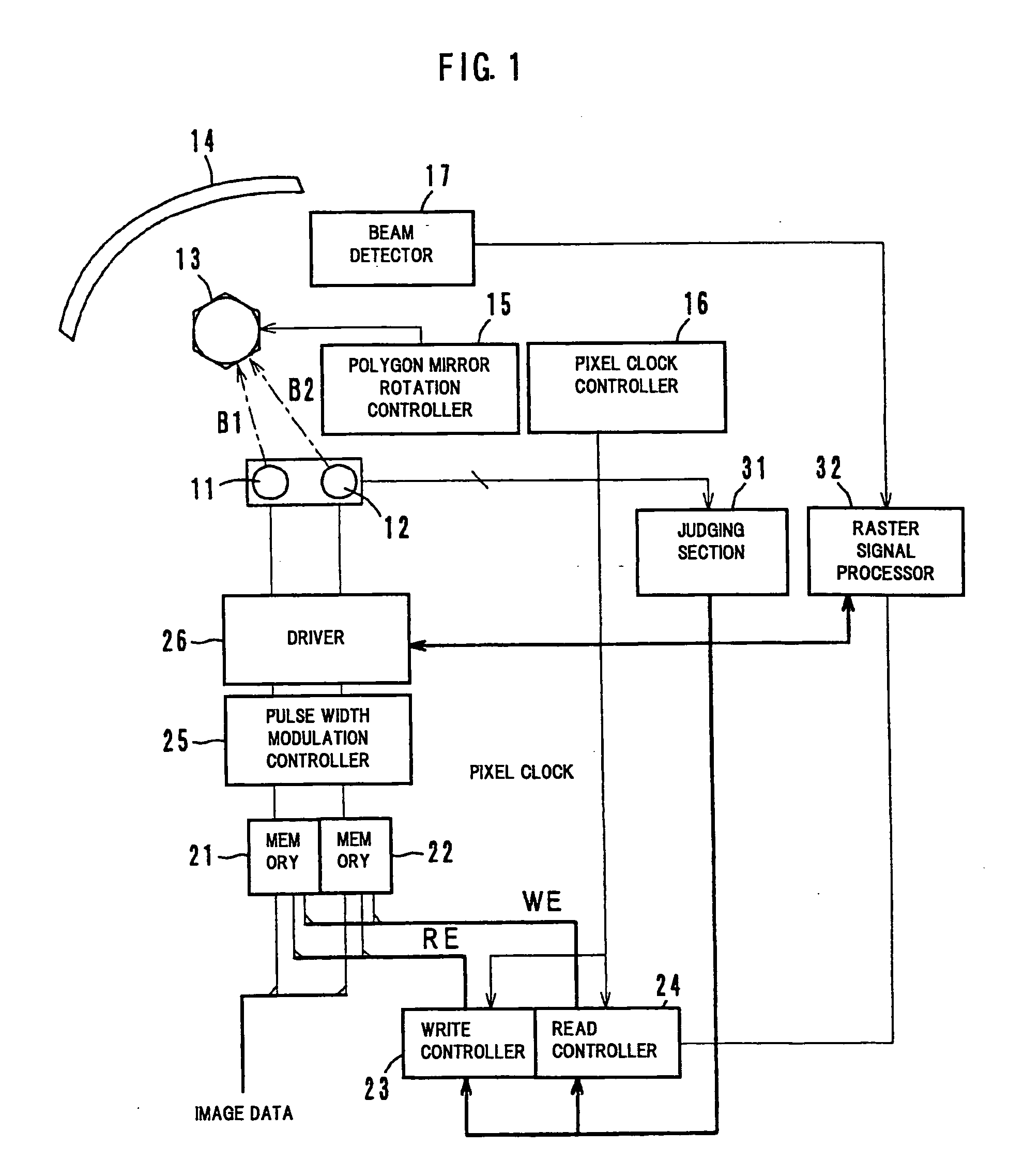
[0027]FIG. 1 shows the essential components of the two-beam scanning optical apparatus according to one embodiment of the present invention. The two-beam scanning optical apparatus shown here employs a two-beam image formation method which forms an image onto a photoconductor drum (not shown) by simultaneously projecting a first beam B1 and a second beam B2 one spaced a prescribed distance apart from the other in the sub-scanning direction. Here, if one of the beams, B1 or B2, fails to be produced properly, image formation is performed by using only the other properly produced beam. The details of this will be described later.

[0028] The first beam B1 and the second beam B2 are emitted from laser diodes 11 and 12 arranged in an array, and are deflected for scanning in the main scanning direction by means of a polygon mirror 1...


PUM


Abstract

A two-beam scanning optical apparatus includes a first beam generating device, a second beam generating device, a judging unit which judges whether the second beam generating device is operating normally or not, a raster signal processing unit which outputs a raster signal each time if the judging unit judges that the second beam generating device is operable, and which outputs a raster signal every other time if the judging unit judges that the second beam generating device is not operable and a control unit which performs image formation by using the first beam generating device and the second beam generating device based on the raster signal output every other time, and which performs image formation by using only the first beam generating device based on the raster signal output each time.

Description

[0001] This application is based on Japanese Patent Application(s) No(s). 2004-217261 filed in Japan on Jul. 26, 2004, the entire content of which is hereby incorporated by reference. BACKGROUND OF THE INVENTION [0002] 1. Field of the Invention [0003] The present invention relates to a two-beam scanning optical apparatus, and more particularly to a two-beam scanning optical apparatus which forms an image on a photoconductor by simultaneously projecting two beams one spaced a prescribed distance apart from the other in a sub-scanning direction. [0004] 2. Description of the Related Art [0005] In the field of electrophotographic image forming apparatus, it has been widely practiced in recent years to form an electrostatic latent image on a photoconductor by using a two-beam scanning optical apparatus equipped with a light emitting device array that emits two beams simultaneously. When provisions are made to form an image by simultaneously projecting two beams one spaced a prescribed di...

Claims


Application Information

Patent Timeline
Patent Type & Authority Applications(United States)
IPC IPC(8): G09G1/04
CPCG02B26/127B41J2/473
Inventor NOGUCHI, KAZUYOSHITAKAHAMA, HIDEKAZUTSUTSUMI, TAKAHIROMAEGAWA, TORU
Owner KONICA MINOLTA BUSINESS TECH INC
Learn More