
Installation structureof in take manifold

a technology for installing structures and intake manifolds, which is applied to air intakes for fuel, machines/engines, combustion air/fuel air treatment, etc., can solve problems such as defective sealing, deformation of the cylinder head, and restricted layout, so as to ensure the mounting strength the operation of the intake manifold

Active Publication Date: 2006-01-26
NISSAN MOTOR CO LTD
View PDF0 Cites 6 Cited by
  • Summary
  • Abstract
  • Description
  • Claims
  • Application Information

AI Technical Summary

Benefits of technology

The present invention provides a mounting structure for an intake manifold that makes it easy to position the flange of the intake manifold and efficiently fit the fitting bolts without requiring additional parts. The structure includes a cylinder head with branch tubes and a plenum chamber portion, and an outwardly projecting arm on the cylinder head with an engaging recess for positioning the bolt holes. The flange is easily placed on the projecting arm and can be moved accurately to its position. The projecting arm is tapered to secure the flange in place and prevent O-rings from dropping out. The plenum chamber portion has flat portions for easy mounting and the intake manifold is securely fixed without requiring additional support. The technical effects of the invention include easy and accurate positioning of the intake manifold and efficient fitting of the bolts.

Problems solved by technology

However, in the case of a resin-made intake manifold, there is a possibility that the flange 7 may cause defective sealing due to secular change of the resin such as creep deformation after tightening the flange 7.
As a result, a problem arises that the O-ring 50 is liable to drop out or suffer damage and to cause a defective sealing.
Accordingly, there is a problem that the layout around the cylinder head is restricted to ensure no interfering object within the space for moving the flange 7.
However, there arises a problem that the structure becomes complicated.

Method used


Image

  • Installation structureof in take manifold
  • Installation structureof in take manifold
  • Installation structureof in take manifold

Examples


Embodiment Construction

[0046] Hereinafter, embodiments of the present invention will be described with reference to the drawings.

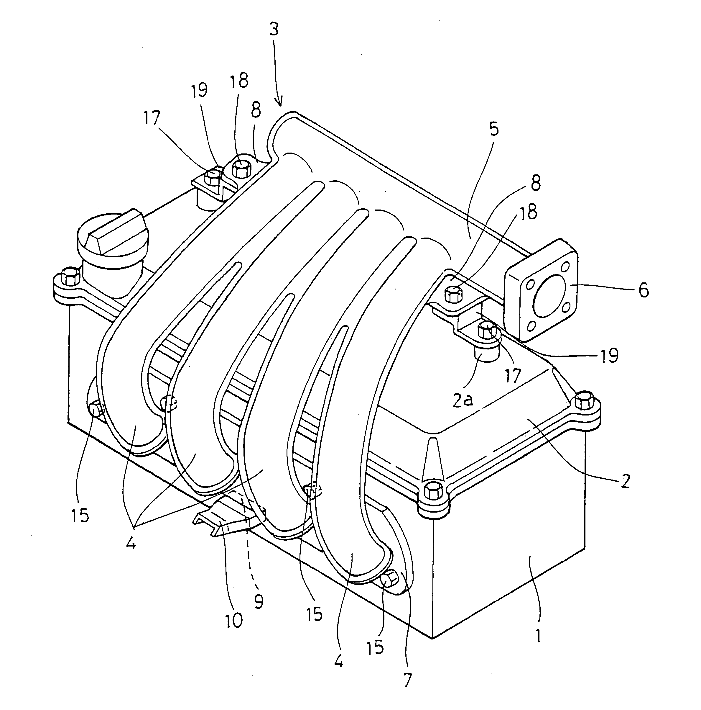
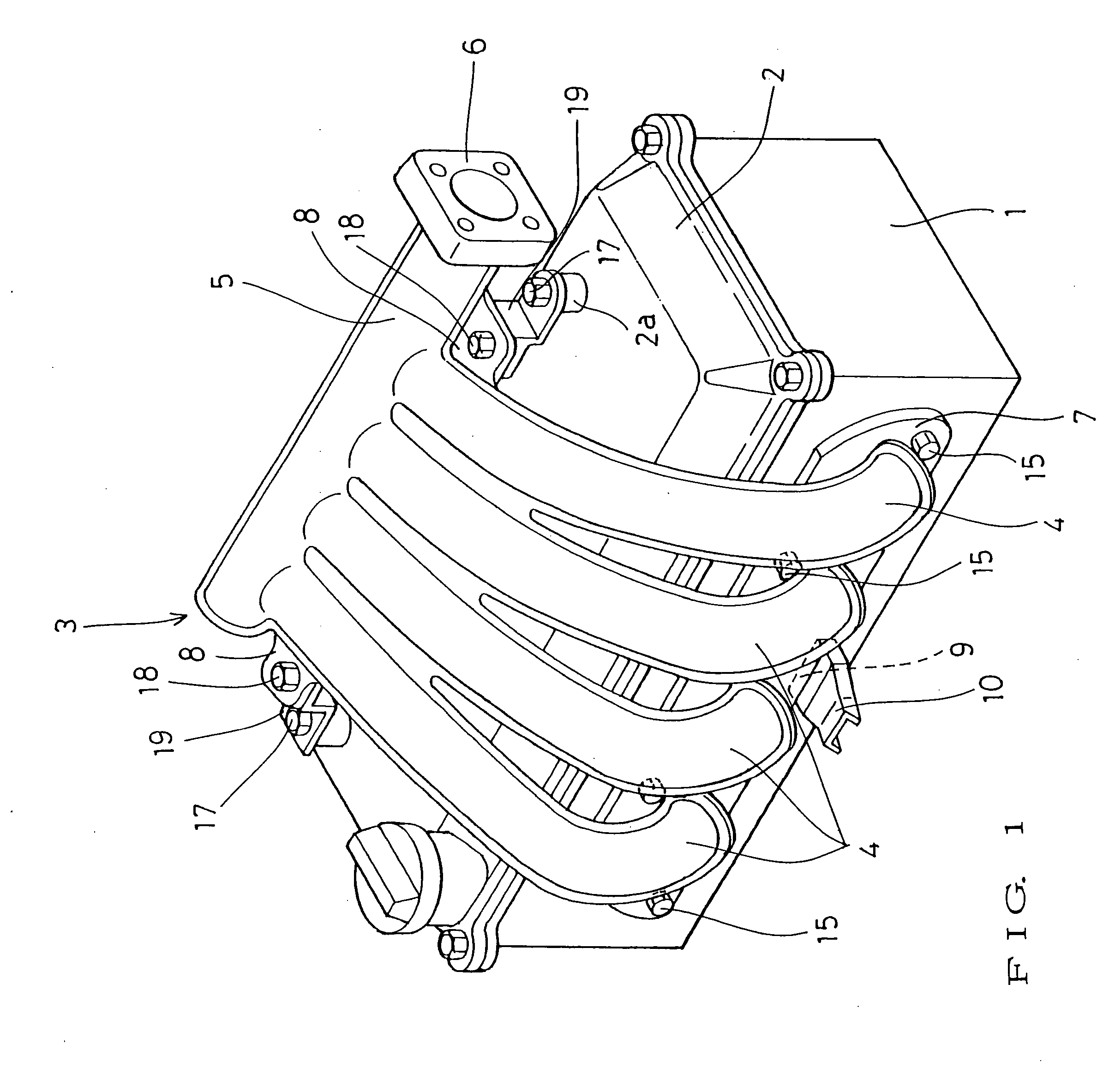
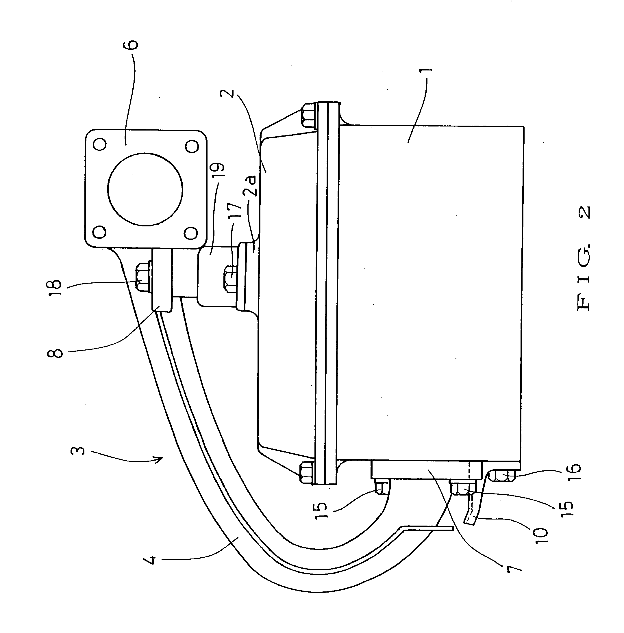
[0047]FIG. 1 is a perspective view of a mounting structure of an intake manifold mounted on a cylinder head. FIG. 2 is a side view, and FIG. 3 is a plan view of the same.

[0048] In the drawings, the top surface of a cylinder head 1 is covered with a rocker cover 2, and an intake manifold 3 is mounted on the lateral side of the cylinder head 1 via a flange 7.

[0049] The intake manifold 3 includes four branch tubes 4 having upstream-side ends to which the flange 7 is mounted. On the upstream-side ends of the branch tubes 4, there is provided a plenum chamber portion 5 having the right end to which a throttle chamber mounting flange 6 is mounted.

[0050] In this embodiment of the intake manifold 3, the right and left outer branch tubes 4, 4 on the side of the plenum chamber 5 are integrally formed with respective flat portions 8, 8 projecting laterally.

[0051] The flat portions 8 a...


PUM

PropertyMeasurementUnit
taper angleaaaaaaaaaa
mounting structureaaaaaaaaaa
sizeaaaaaaaaaa

Abstract

In an intake manifold 3 having a plurality of branch tubes 4, 4 arranged over the top surface of a cylinder head 1 in a state were a flange 7 provided at downstream-side ends of the branch tubes 4, 4 is fixed to a lateral surface of the cylinder head 1, and having a plenum chamber portion 5 provided at upstream-side ends of the branch tubes 4, 4, a retainer 10is provided on the lateral surface of the cylinder head 1 and projecting outward therefrom, and an engaging recess 9 is provided in the lower portion of the flange 7 in order to engage with the retainer 10. Further, in the plenum chamber portion 5 of the intake manifold 3, flat portions 8, 8 are formed and are permitted to be provisionally placed on and fixed in position relative to the top surface of a rocker cover 2.

Description

[0001] The present invention relates to a mounting structure of an intake manifold. PRIOR ART [0002] Conventionally, an intake manifold is mounted on a cylinder head, as shown by the perspective view FIG. 11, by the side view in FIG. 12, and by the plan view in FIG. 13. [0003] The intake manifold 3 has a plurality of branch tubes 4 that have a plenum chamber portion 5 at their upstream-side ends. A throttle chamber mounting flange 6 is mounted to a lateral surface of the plenum chamber portion 5. A flange 7 is mounted to downstream-side ends of the branch tubes 4. This flange 7 is fixedly mounted to the lateral surface of the cylinder head 1 via a flange mounting bolt 15. [0004] A rocker cover 2 is provided on the top of the cylinder head 1. In the mounted state, the branch tubes 4 extend from the lateral surface of the cylinder head 1 over the rocker cover 2, and the plenum chamber portion 5 is supported by a vertical intake-manifold support 51 that extends vertically from the late...

Claims


Application Information

Patent Timeline
Patent Type & Authority Applications(United States)
IPC IPC(8): F02M35/10F02M35/104
CPCF02M35/10052F02M35/10072F02M35/10078F02M35/112F02M35/10321F02M35/10354F02M35/10111F02M35/10
Inventor KOGAWA, YOUICHI
Owner NISSAN MOTOR CO LTD
Learn More