
Sandwich panel and method of manufacturing same

a technology of sandwich panels and manufacturing methods, applied in the field of sandwich panels, can solve the problems of undue flex lack of rigidity or atmospheric stability of typical solid or single layer panels, and inability to maintain the desired shape of typical load panels, etc., to achieve the effect of improving reliability, improving reliability, and improving fit and finish of the panel

Inactive Publication Date: 2006-01-12
GRUPO ANTOLIN NORTH AMERICA
View PDF5 Cites 29 Cited by
  • Summary
  • Abstract
  • Description
  • Claims
  • Application Information

AI Technical Summary

Benefits of technology

[0010] Another embodiment comprises two skins attached to an intermediate substrate forming a structural panel further including an edge member. The edge member may include an engaging member that mechanically engages the intermediate substrate. The engaging member may also have anti-reverse fins that prevent the engaging member from backing out of the intermediate substrate. Further, a covering material may be selectively applied to the skins for improved reliability or for cosmetic appearance. The edge member may also trap a portion of the covering material to improve reliability and improve fit and finish of the panel.

Problems solved by technology

However, typical load panels have undue flex when supporting large weights.
Additionally, typical panels do not maintain their desired shape under changes in atmospheric conditions such as temperature and humidity.
The typical solid or single layer panels do not have the rigidity or atmospheric stability required for the harsh automotive environment.
Additionally, typical panels do not include finished edges or edges that trap covering material at the edges to reduce peeling or separation of covering material.

Method used


Image

  • Sandwich panel and method of manufacturing same
  • Sandwich panel and method of manufacturing same
  • Sandwich panel and method of manufacturing same

Examples


Embodiment Construction

[0019] Referring now to the drawings, the preferred illustrative embodiments of the present invention are shown in detail. Although the drawings represent some preferred embodiments of the present invention, the drawings are not necessarily to scale and certain features may be exaggerated to better illustrate and explain the present invention. Further, the embodiments set forth herein are not intended to be exhaustive or otherwise limit or restrict the invention to the precise forms and configurations shown in the drawings and disclosed in the following detailed description.

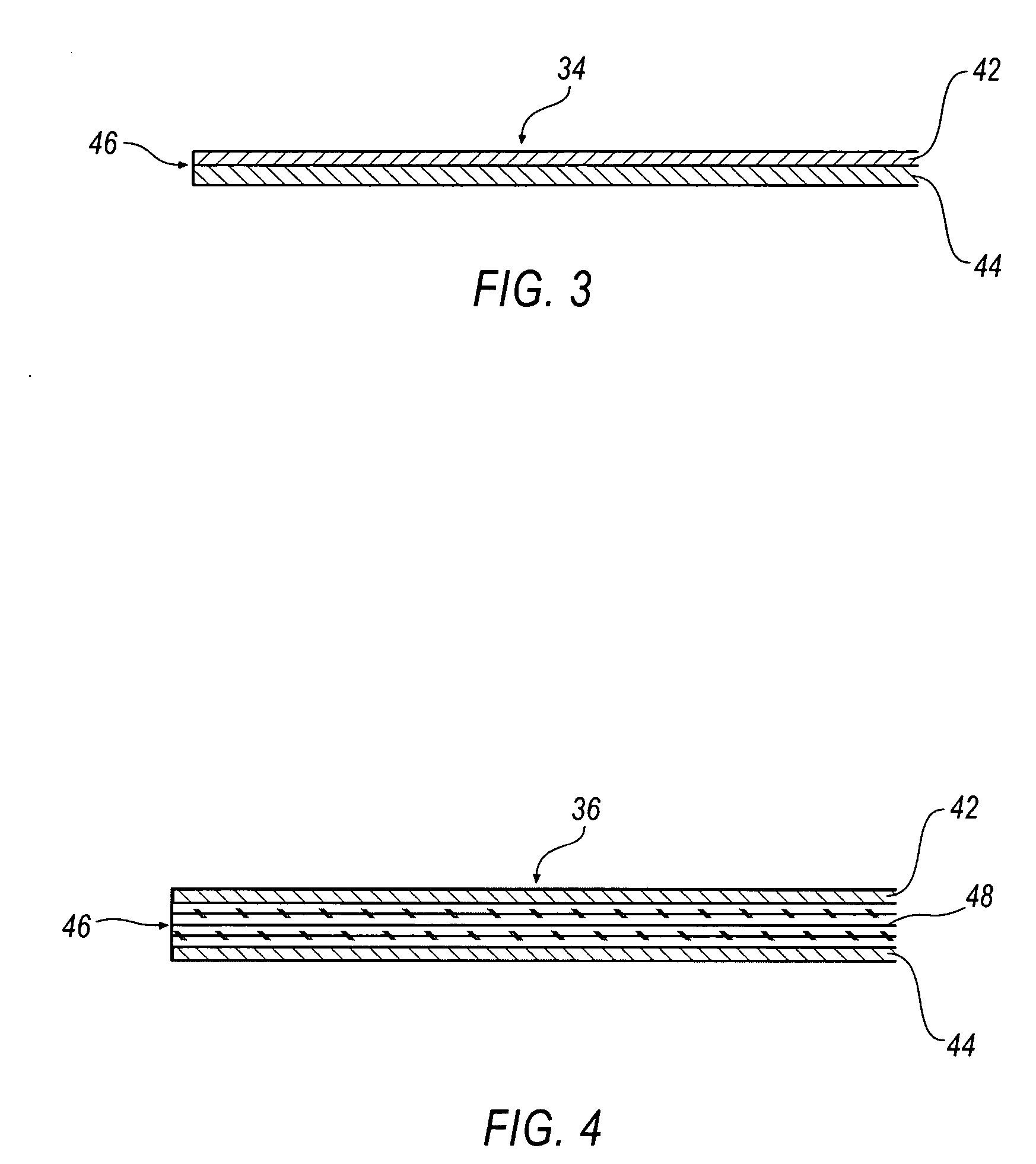
[0020]FIG. 3 illustrates a cross sectional view of a two layer sandwich panel 34 according to an embodiment of the present invention. Panel 34 includes at least two substrates or skins 42, 44. The skins 42, 44 may be fixed to one another using adhesive or other fastening methods. The sandwich of skins 42, 44 improves the strength, stiffness, and dimensional stability of the panel over various atmospheric conditi...


PUM

PropertyMeasurementUnit
Sizeaaaaaaaaaa
Shapeaaaaaaaaaa

Abstract

A sandwich panel having a pair of skins and an intermediate substrate secured between the two skins creating a structural panel. The skins may be a pressboard material and a covering material may be applied to the skins forming an exterior surface. Selectively, the skins may be covered with a material. Further, an edge member may be provided that is engaged around the peripheral edge of the intermediate substrate. The edge member may include an engaging member and the engaging member may include anti-reverse fins. The edge member may also trap the covering material. A method of manufacturing a sandwich panel for an automobile where two skins of predetermined size and shape are provided. The two skins are attached to each other forming a structural panel. An intermediate substrate may be provided and attached between the skins. Further, an edge member may be provided and attached to the periphery of the structural panel.

Description

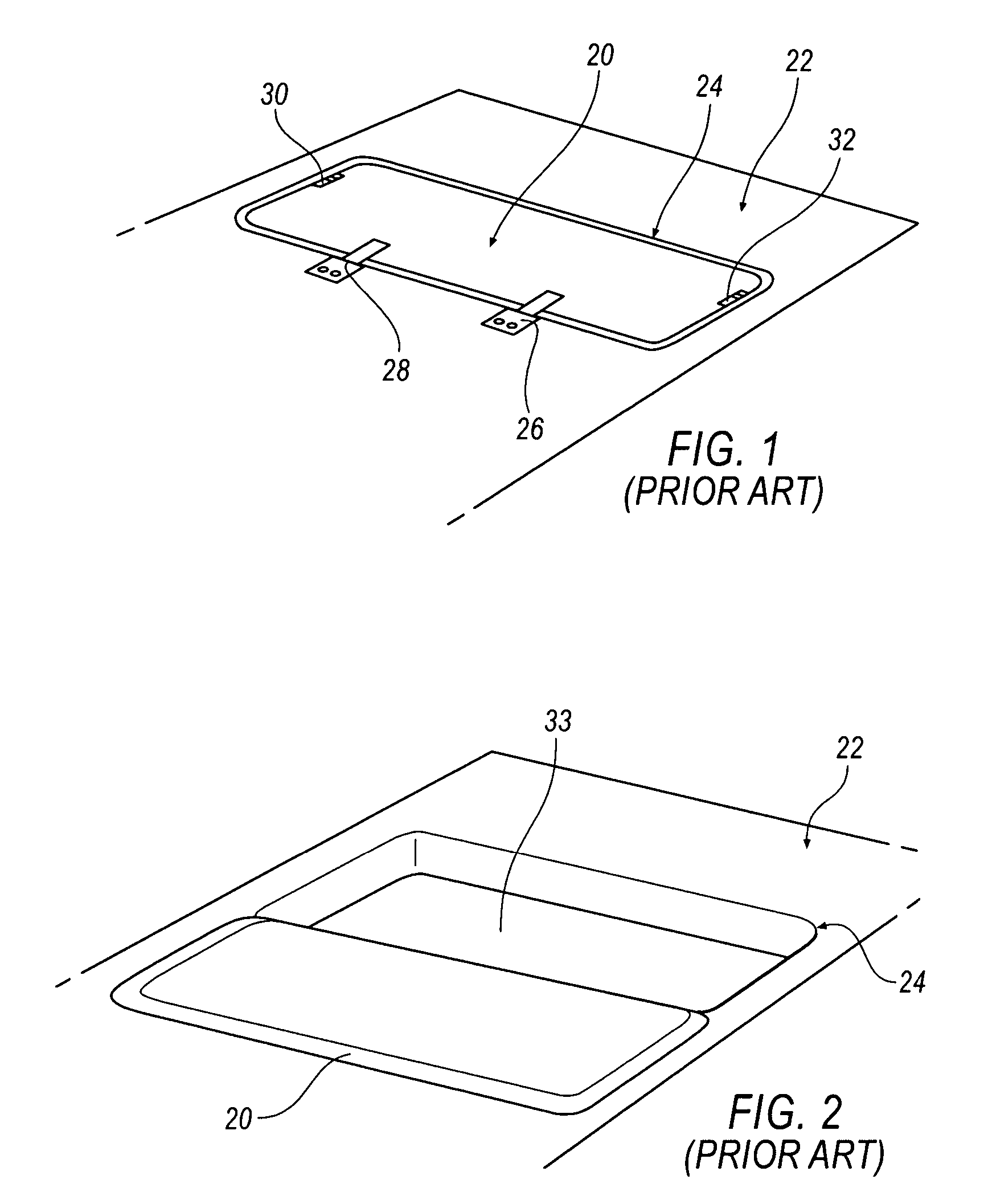
CROSS REFERENCE TO RELATED APPLICATIONS [0001] This application claims the benefit of U.S. Provisional Application No. 60 / 539,517 filed Jan. 26, 2004, the entire contents of which are herein incorporated by reference.BACKGROUND OF THE INVENTION [0002] 1. Field of the Invention [0003] The present invention relates to a sandwich panel and method of manufacturing a sandwich panel and, more particularly, to a sandwich panel and method of manufacturing a sandwich panel for use as a structural member. [0004] 2. Description of the Related Art [0005] Load panels are used for covering storage areas and supporting weight in applications such as automotive interiors and storage spaces. Common uses include load floors, bay covers, flipper panels, seat backs, and cargo cabinets. Solid material panels are used for typical load panels in addition to blow molded panels. [0006] A known prior art load panel is shown in FIGS. 1 and 2. FIG. 1 illustrates a typical single layer structural panel 20 in a ...

Claims


Application Information

Patent Timeline
IPC IPC(8): B32B3/10B32B7/08B32B29/00B32B23/04
CPCB32B21/00Y10T428/16Y10T428/169B60R13/011Y10T428/31971Y10T428/249987
Inventor SNYDER, GLENN E.BOYLE, KEITH R.CROTTY, WILLARD E. III
Owner GRUPO ANTOLIN NORTH AMERICA
Learn More