
3D kernel and prism assembly design

a technology of 3d kernels and prisms, applied in the field of projection monitors, displays, televisions, etc., can solve the problems of high cost and wdws, and achieve the effects of cost saving, easy line-up and attachment, and easy production of kernels

Inactive Publication Date: 2006-01-12
LIGHTMASTER SYST
View PDF9 Cites 11 Cited by
  • Summary
  • Abstract
  • Description
  • Claims
  • Application Information

AI Technical Summary

Benefits of technology

[0009] The present inventors have realized several needs for greater flexibility in the design of light engine kernels and prism assemblies. One of the needs is cost based in that certain components, such as WDWs, that are expensive to procure. A prism assembly and kernel designs with a reduced number, or free of WDWs potentially represents a significant cost savings in materials and manufacturing expenses.
[0022] The present inventors have also realized the placement and orientation of light modulators (e.g., reflective microdisplays) has significant impact on the ease of production of kernels. Therefore, significant cost savings can be gained from an orientation of microdisplays such that flex-tail portions common to modern microdisplay devices are easily lined up and attached to PCB components (e.g., a drive board) that provide video or other image signals to control modulation of light to the microdisplays. In one embodiment, the present invention is an orientation of microdisplays such that no more than a single 90 degree bend is required in only one of the microdisplay flex tails.

Problems solved by technology

One of the needs is cost based in that certain components, such as WDWs, that are expensive to procure.

Method used


Image

  • 3D kernel and prism assembly design
  • 3D kernel and prism assembly design
  • 3D kernel and prism assembly design

Examples


Embodiment Construction

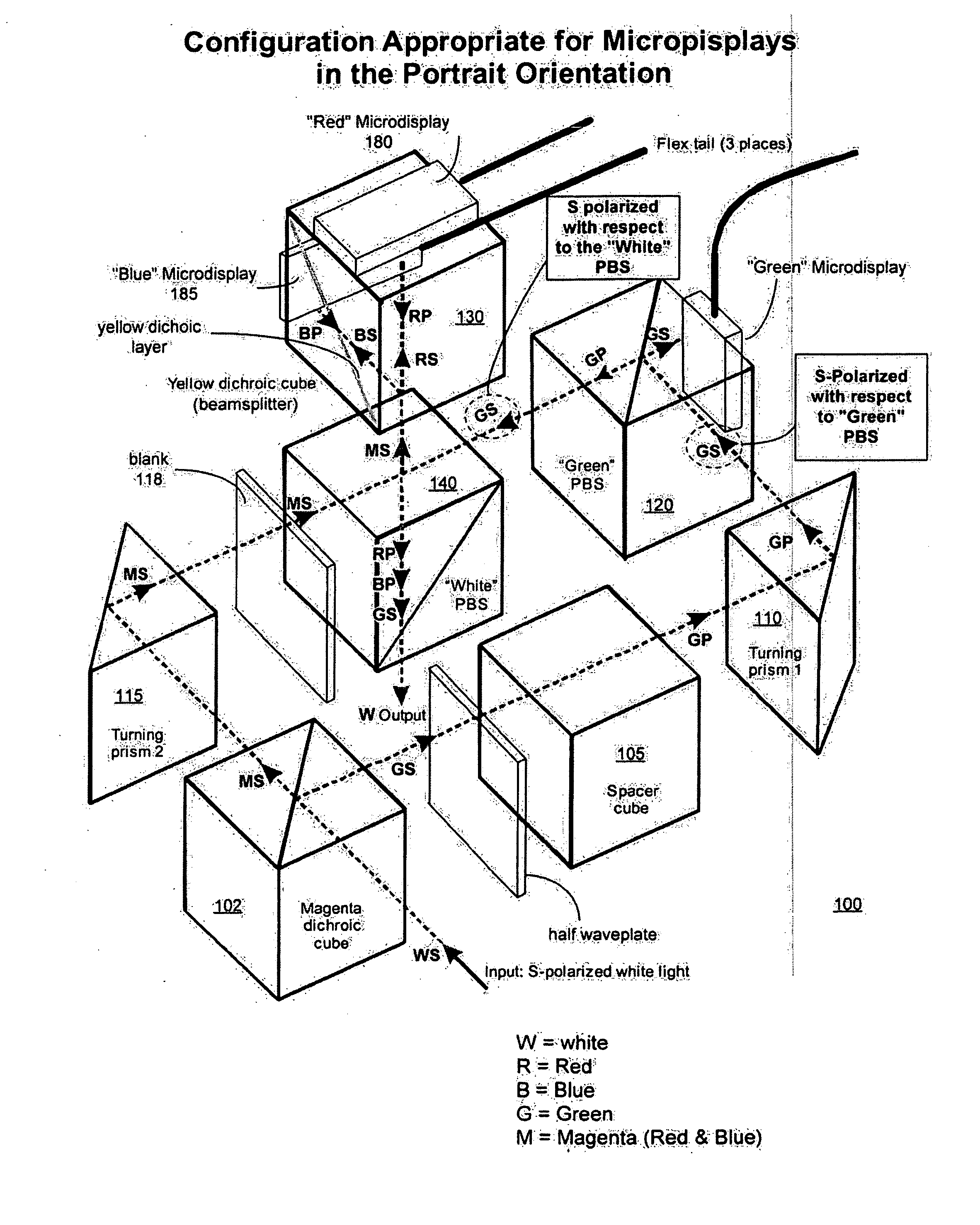
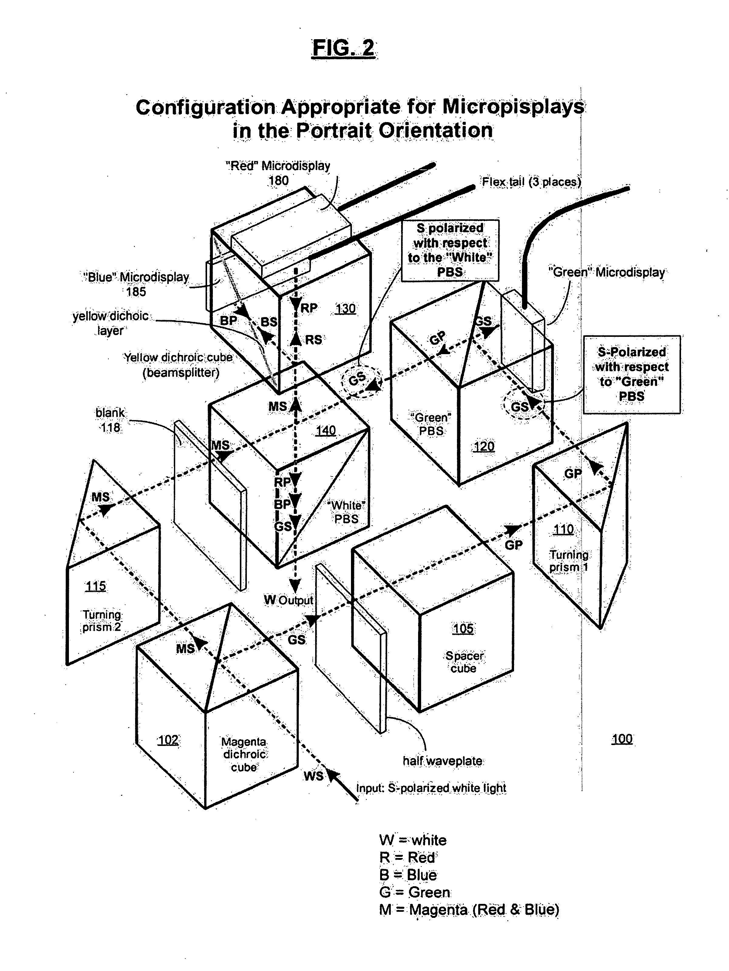
[0026]FIG. 2 a prism assembly 100 and kernel configuration (prism assembly plus attached microdisplays). Each component is named and the path and polarization of the light at each point within the prism assembly 100 is indicated. The color (e.g., R—red; G—green; B—Blue) indicates the color [or band] of the light ray. S and P represent the relative polarizations of the light (e.g., GS=Green light having a S relative polarization).

[0027] The prism assembly is composed of a number of transparent or glass optical components (e.g., 102, 105, 110, 115, 120, 130, and 140). Glass utilized in the prism assembly preferably has a low photoelastic constant. This assures that any stress built into or that develops during operation of the prism assembly will not induce birefringence or result in the introduction of visual artifacts in the image.

[0028] Upon detailed review of the present disclosure, it will be understood that certain parts utilized in the illustrated embodiments may substituted ...


PUM


Abstract

A Liquid Crystal on Silicon (LCOS) kernel for a light engine is configured in a kernel having light paths in three dimensions (3D kernel). The 3D kernel allows for designs that do not require Wavelength Dependent Waveplates (WDWS) (or Wavelength Specific Retarders) for managing light polarizations within the 3D kernel. In one embodiment, the 3D kernel includes a Polarizing Beam Splitter (PBS) that is positioned to direct lightpaths within the 3D kernel in the 3rd dimension (e.g., light path planes perpendicular to planes of input light provided to the 3D kernel). The 3rd dimension is, for example, an output light path perpendicular to an input light plane. The 3D kernel allows for designs that incorporate reflective LCOS microdisplays and management of light paths without WDWs. The kernel is suitable for use in High Definition (HD) LCOS Rear Projection Televisions (RPTVs) and other projector applications.

Description

CROSS REFERENCE TO RELATED APPLICATIONS AND CLAIM OF PRIORITY [0001] This invention claims priority to the following co-pending U.S. provisional patent application, which is incorporated herein by reference, in its entirety: [0002] Berman, Provisional Application Ser. No. 60 / 587,616, entitled “A 3d Kernel and Prism Assembly Design,” attorney docket no. 356508.03800, filed, 7 / 12 / 04.COPYRIGHT NOTICE [0003] A portion of the disclosure of this patent document contains material which is subject to copyright protection. The copyright owner has no objection to the facsimile reproduction by anyone of the patent document or the patent disclosure, as it appears in the Patent and Trademark Office patent file or records, but otherwise reserves all copyright rights whatsoever. BACKGROUND OF THE INVENTION [0004] 1. Field of Invention [0005] The present invention relates to projection monitors, displays, televisions, and other display systems. The invention is more particularly related to a kernel...

Claims


Application Information

Patent Timeline
Patent Type & Authority Applications(United States)
IPC IPC(8): G03B21/00
CPCG02B5/3016G02B27/283G03B21/2073H04N9/315H04N9/3197H04N9/3105
Inventor BERMAN, ARTHUR
Owner LIGHTMASTER SYST
Learn More