
Power supply apparatus for vehicle

Active Publication Date: 2006-01-12
SANYO ELECTRIC CO LTD
View PDF1 Cites 43 Cited by
  • Summary
  • Abstract
  • Description
  • Claims
  • Application Information

AI Technical Summary

Benefits of technology

[0005] The present invention has been developed for solving the disadvantage. It is an important object of the present invention to provide a power supply apparatus for a vehicle that uses a voltage detection circuit previously provided in the power supply apparatus, thus can accurately detect a leakage resistance between the output side of a driving battery and a chassis, and does not require a complex circuit configuration nor a dedicated voltage detection circuit.
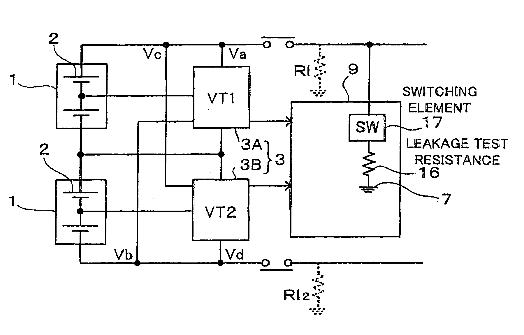
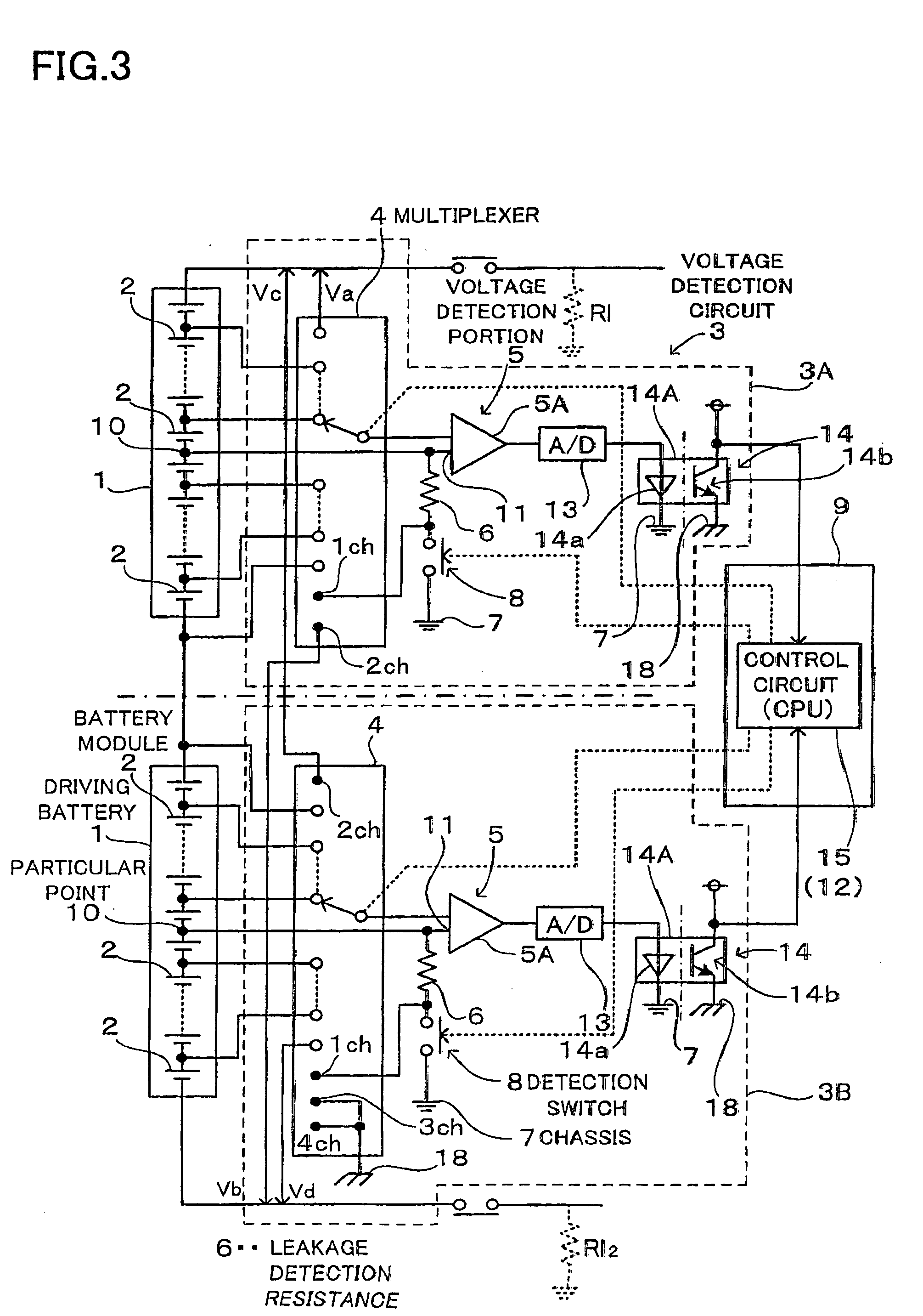
[0014] The aforementioned power supply apparatus for a vehicle has an advantage that can accurately detect a leakage resistance between the output side of a driving battery and a chassis without a complex circuit configuration. The reason is that, in the power supply apparatus for a vehicle according to the present invention, the particular point of battery module of the driving battery is connected to the chassis through the leakage detection resistance, and the voltage detection circuit detects a chassis voltage that is inducted to the both ends of the leakage detection resistance by switching the multiplexer of the voltage detection circuit that detects a battery voltage of the driving battery to detect a leakage resistance based on the chassis voltage. That is, the power supply apparatus for a vehicle according to the present invention uses a voltage detection circuit previously provided in the power supply apparatus to detect a battery voltage of the driving battery, and detects a leakage resistance between the output side of the driving battery and the chassis without a dedicated voltage detection circuit that detects the leakage resistance. Therefore, since its circuit configuration is simple, it is possible to reduce producing cost, and additionally the power supply apparatus for a vehicle according to the present invention reliably detects a leakage of a driving battery.

Problems solved by technology

For this reason, this type of device has a disadvantage that the circuit configuration is complex to detect a leakage resistance.

Method used


Image

  • Power supply apparatus for vehicle
  • Power supply apparatus for vehicle
  • Power supply apparatus for vehicle

Examples


Embodiment Construction

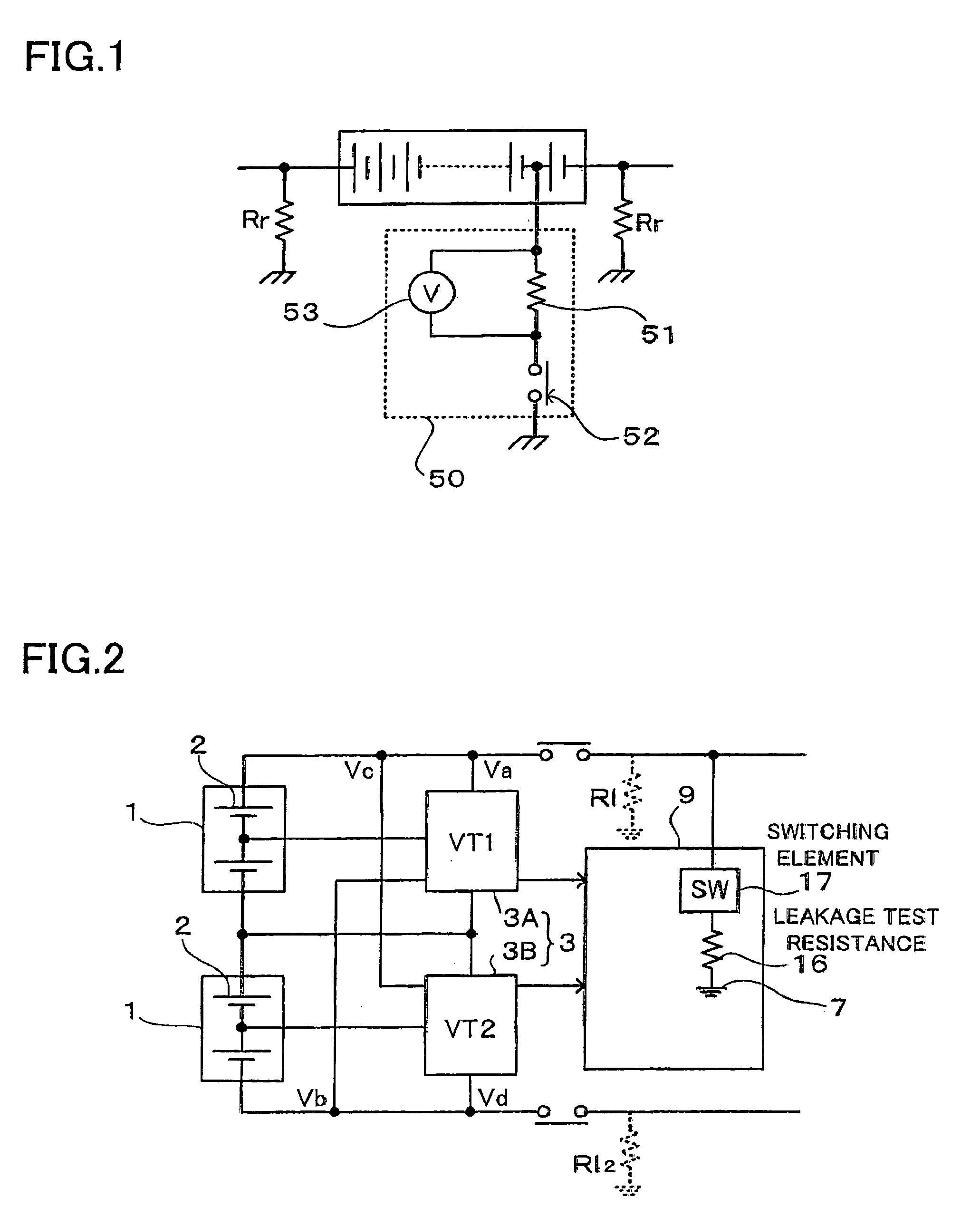
[0027] A power supply apparatus as shown in FIGS. 2 and 3 comprises a driving battery 1 including a plurality of battery modules 2 that are connected to each other in series, and a voltage detection circuit 3 that detects a battery voltage of the driving battery 1.

[0028] The voltage detection circuit 3 comprises a multiplexer 4 that switches the plurality of battery modules 2 in a time sharing manner, a voltage detection portion 5 that detects the voltages of the battery modules 2 selected by the multiplexer 4, and a detection switch 8 that connects a particular point 10 of battery module 2, i.e., a reference input terminal 11 of the voltage detection portion 5 connected to the particular point 10, to a chassis 7 through a leakage detection resistance 6 only in detection of a leakage resistance.

[0029] The voltage detection circuit 3 is a circuit that is equipped with the power supply apparatus to detect the voltages of all the battery modules 2. For example, in the case where the ...


PUM


Abstract

A power supply apparatus for a vehicle comprises a voltage detection circuit that detects voltages of a plurality of battery modules. The voltage detection circuit comprises a multiplexer that switches the battery modules voltages of which are detected in a time sharing manner, and a voltage detection portion that detects the voltages of the battery modules switched by the multiplexer. In the power supply apparatus, a particular point of the battery module is connected to a chassis through a leakage detection resistance, and the voltage detection circuit detects a chassis voltage that is inducted to the both ends of the leakage detection resistance by switching the multiplexer of the voltage detection circuit to detect a leakage resistance based on the chassis voltage.

Description

BACKGROUND OF THE INVENTION [0001] The present invention relates to a power supply apparatus that drives a motor for running an electric vehicle, such as hybrid car and electric car, and particularly to a power supply apparatus for a vehicle capable of accurately detecting a leakage that occurs in the output side of a driving battery with simple circuit configuration. [0002] High voltage is required to increase the output of a power supply apparatus for driving an electric vehicle. The reason is that the output is proportional to the product of a voltage and a current, and that a higher voltage provides an advantage when a motor is driven. For example, the output voltage of a power supply apparatus for driving a hybrid car or an electric car is very high voltage of 200 V or more. Since workers may receive an electric shock if they touch a high voltage power supply apparatus in maintenance, the high voltage power supply apparatus is not connected to a chassis in terms of safety. For ...

Claims


Application Information

Patent Timeline
IPC IPC(8): H02J7/00
CPCB60R16/03H02J7/0021Y02T10/7055B60L3/0046B60L2240/547B60L3/12B60L11/1859B60L11/1864B60L3/0069B60L58/14B60L58/21B60L58/15B60L58/18H02J2310/46Y02T10/70H02J7/0013H02J7/0048
Inventor FURUKAWA, KIMIHIKO
Owner SANYO ELECTRIC CO LTD
Learn More