Snap-in cable connector
a technology of cable connector and clamping pin, which is applied in the direction of coupling device connection, electrical discharge tube, multi-purpose tools, etc., can solve the problems of occupying valuable space in the electrical box, requiring a shorter fastener, and the electrical box lacking adequate clearance between the cables and devices
- Summary
- Abstract
- Description
- Claims
- Application Information
AI Technical Summary
Benefits of technology
Problems solved by technology
Method used
Image

Examples
second embodiment
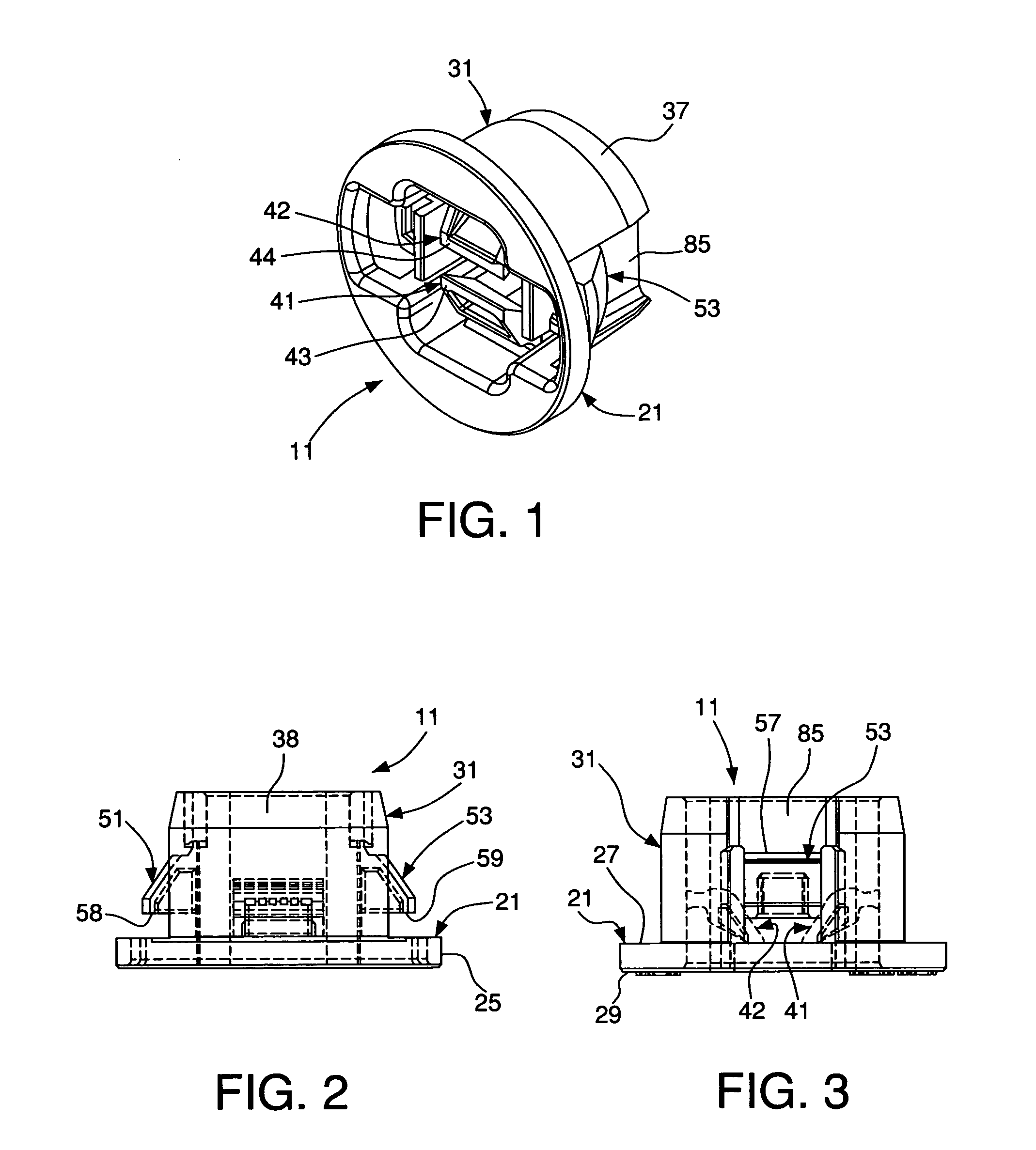
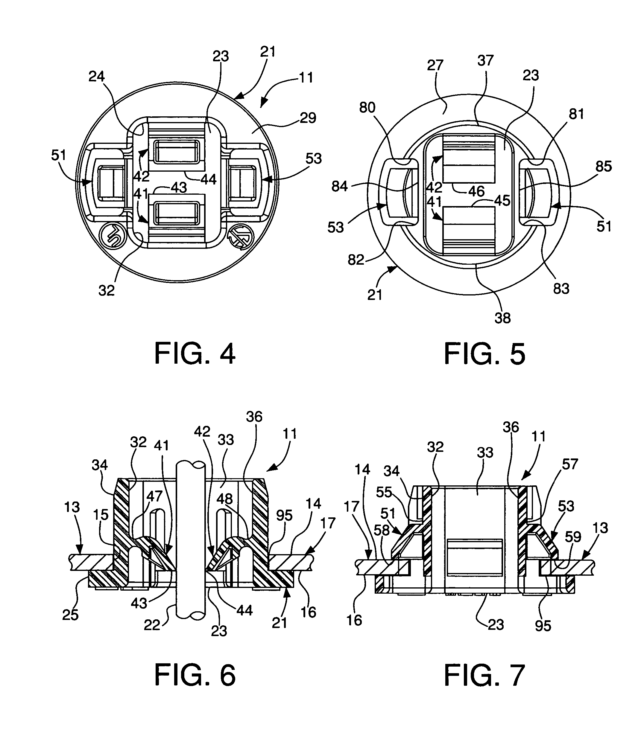
[0043] an electrical connector 211 according to the present invention is shown in FIGS. 8-13, 20 and 21, and is similar to the connector 11 described above. However, in FIGS. 8-13, 20 and 21, the first and second tabs 251 and 253 have lower edges 258 and 259 that are angled, as shown in FIG. 13. Preferably, the lower edges 258 and 259 angle upwardly away from the upper surface 227 of the base 221. The angled lower edges 258 and 259 allow the electrical connector 211 to be secured to support walls of various thicknesses. The angled lower edges 258 and 259 allow the first and second tabs 251 and 253 to accommodate a larger range of wall thicknesses than non-angled lower edges, such as lower edges 58 and 59 shown in FIG. 2. Preferably, the angle “a” (FIG. 13) of the lower edges is approximately 13 degrees. The distal ends 245 and 246 of first and second fingers 241 and 242 have recesses 249 and 250 adapted to receive substantially round cables. The rounded or arcuate recesses 249 and 2...
third embodiment
[0045] an electrical connector 311 according to the present invention is shown in FIGS. 14-19 and 21, and is similar to connectors 11 and 211 described above. The first and second tabs 351 and 353 have lower edges 358 and 359 that are angled, as shown in FIG. 19, which is similar to that shown in FIG. 13. Preferably, the lower edges 358 and 359 angle upwardly away from the upper surface 327 of the base 321. The angled lower edges 358 and 359 allow the electrical connector 311 to be secured to support walls of various thicknesses. The angled lower edges 358 and 359 allow the first and second tabs 351 and 353 to accommodate a larger range of wall thicknesses than non-angled lower edges, such as lower edges 58 and 59 shown in FIG. 2. Preferably, the angle “b” of the lower edges is approximately 13 degrees, unlike connectors 11 and 211. The distal ends 345 and 346 of first and second fingers 341 and 342 of connector 311 have recesses 349 and 350 adapted to receive substantially round ca...
PUM
 Abstract
Description
Claims
Application Information
 - R&D
- Intellectual Property
- Life Sciences
- Materials
- Tech Scout
- Unparalleled Data Quality
- Higher Quality Content
- 60% Fewer Hallucinations
Browse by: Latest US Patents, China's latest patents, Technical Efficacy Thesaurus, Application Domain, Technology Topic, Popular Technical Reports.
© 2025 PatSnap. All rights reserved.Legal|Privacy policy|Modern Slavery Act Transparency Statement|Sitemap|About US| Contact US: help@patsnap.com