Eureka AIR delivers breakthrough ideas for toughest innovation challenges, trusted by R&D personnel around the world.

Power circuit breakers with offset vertical quick disconnect adapters to allow plugging onto a line and a load bus in different planes

a technology of power circuit breakers and adapters, which is applied in the direction of contacts, substation/switching arrangement casings, contacts, etc., can solve the problems of requiring the vertical riser to be set back in the housing, affecting the use of many bus assemblies, and affecting the operation of the circuit breaker

Inactive Publication Date: 2006-01-05
EATON CORP
View PDF13 Cites 14 Cited by
  • Summary
  • Abstract
  • Description
  • Claims
  • Application Information

AI Technical Summary

Benefits of technology

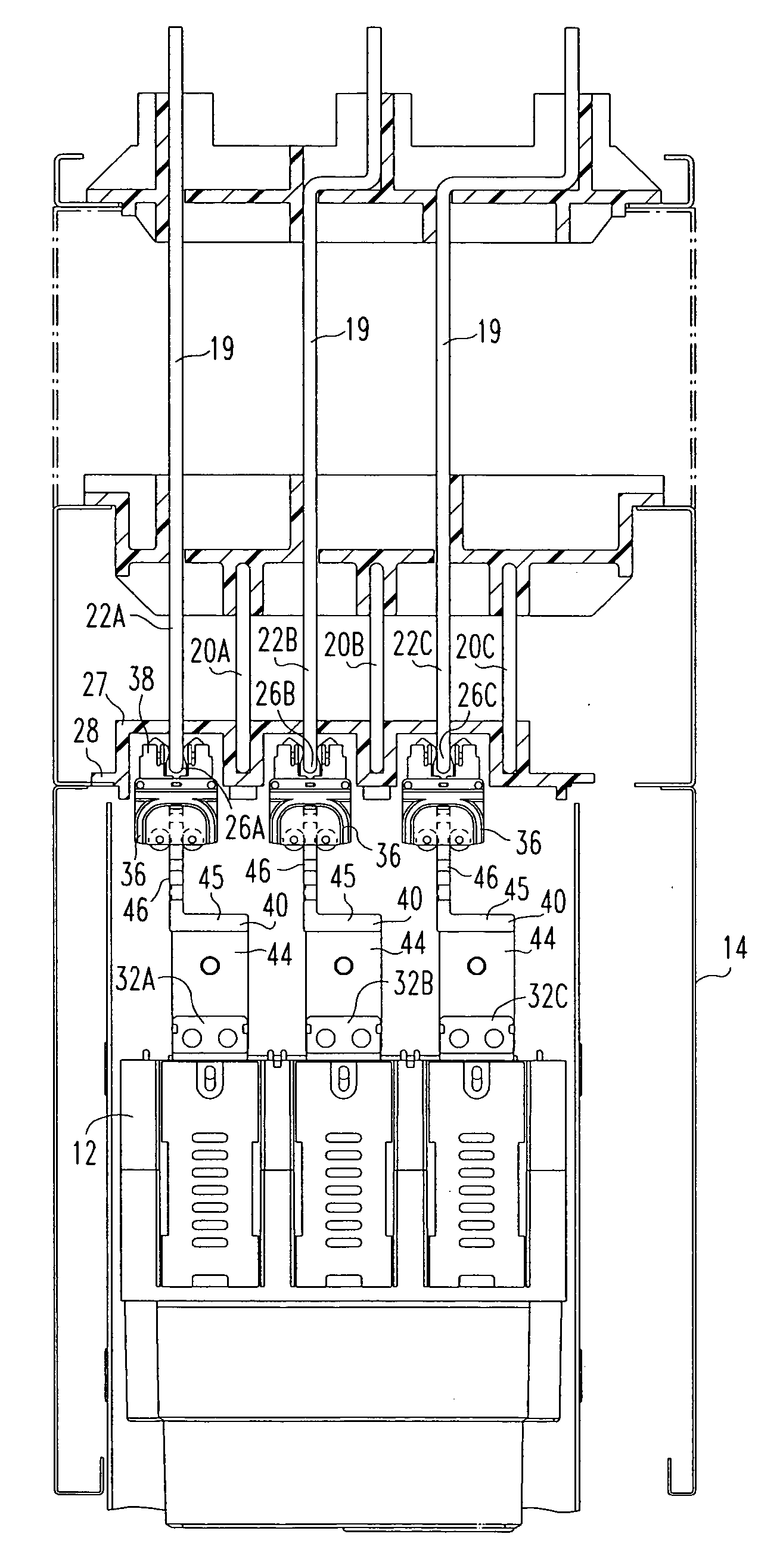
[0013] The circuit breaker is, preferably, a three-pole circuit breaker having three pairs of line and load terminals. The line and load terminals in each pair are generally vertically aligned. Additionally, the pairs of terminals are generally evenly spaced apart. The spacing between the centerline of adjacent pairs of terminals is hereinafter referred to as a “pole spacing unit.” The circuit breaker is structured to be mounted in a housing assembly and supported on rollers which permit easy installation and removal of the circuit breaker in the housing assembly. The circuit breaker terminals are structured to be coupled, via the offset assembly, to quick disconnects. The quick disconnects are structured to engage the bus assembly as the circuit breaker is moved into the housing assembly.

Problems solved by technology

This design, however, incurs more production costs than the use of a solid riser and is prone to overheating where the cross-sectional area of the vertical riser is reduced.
This configuration has the disadvantage of requiring the vertical riser to be set back in the housing.
As bus assemblies typically have the front edge of the vertical risers and runbacks laterally aligned, the bent stab device may not be used with many bus assemblies.
Moreover, as only one set of conductors is set back, the bent stab may not be used on the terminal coupled to the forward conductors.

Method used


Image

  • Power circuit breakers with offset vertical quick disconnect adapters to allow plugging onto a line and a load bus in different planes
  • Power circuit breakers with offset vertical quick disconnect adapters to allow plugging onto a line and a load bus in different planes
  • Power circuit breakers with offset vertical quick disconnect adapters to allow plugging onto a line and a load bus in different planes

Examples


Embodiment Construction

[0025] As shown in FIG. 1, a power circuit breaker assembly 10 includes a circuit breaker 12 and a housing assembly 14. The housing assembly 14 includes outer walls 16 structured to enclose the circuit breaker 12, a bus assembly 18, and a non-conductive shroud (FIG. 2). The bus assembly 18 includes a plurality of conductive members 19 including at least one vertical riser 20 and at least one runback 22. Where the circuit breaker 12 is a three-pole circuit breaker, as is preferred, the bus assembly 18 includes three vertical risers 20A, 20B, 20C and three runbacks 22A, 22B, 22C. The vertical risers 20A, 20B, 20C are made from an elongated, generally flat conductive material, such as, but not limited to, a copper bar. The longitudinal axis of each vertical riser 20A, 20B, 20C extends vertically through the housing assembly 14. The vertical riser 20A, 20B, 20C extends from below the circuit breaker 12 to a point above the circuit breaker 12. The lateral axis of each vertical riser 20A,...


PUM


Abstract

An offset assembly for a circuit breaker includes at least one two plane member having a first plate and a second plate. The first and second plates are joined at an edge and extend generally perpendicular to each other. The second plate is structured to be coupled to the quick disconnect and the first plate is structured to be coupled to the circuit breaker terminal so that the second plate is not aligned with the centerline of the circuit breaker terminal.

Description

BACKGROUND OF THE INVENTION [0001] 1. Field of the Invention [0002] The present invention relates to a circuit breaker having vertically aligned line and load terminals coupled to quick disconnects structured to engage a bus assembly having vertical risers interspersed with horizontal runbacks and, more specifically, to an offset assembly structured to be couple to the line and load terminals to align the quick disconnects with the alternating vertical risers and horizontal runbacks. [0003] 2. Background Information [0004] Low voltage circuit breakers used in electric power distribution systems are commonly mounted in a housing assembly and supported on rollers which permit easy installation and removal of the sizeable circuit breakers required for such service. The housing assembly has walls forming an enclosure and a bus assembly. The bus assembly includes line and load conductors for each pole of the circuit breaker. Each line conductor, or “riser,” is, essentially, an elongated ...

Claims


Application Information

Patent Timeline
Patent Type & Authority Applications(United States)
IPC IPC(8): H02B1/20
CPCH02B11/04
Inventor ABRAHAMSEN, MICHAEL HOWARDROWE, NEAL EDWARDMOORE, STANLEY ERVINFAIR, TIMOTHYSCOTT, MARLYCE JEAN
Owner EATON CORP
Why Eureka
Eureka Blog
Learn More