
Processing logic modeling and execution

Inactive Publication Date: 2005-12-29
IBM CORP
View PDF26 Cites 19 Cited by
  • Summary
  • Abstract
  • Description
  • Claims
  • Application Information

AI Technical Summary

Benefits of technology

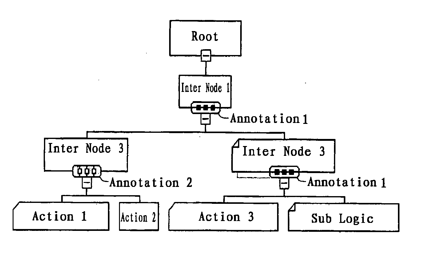
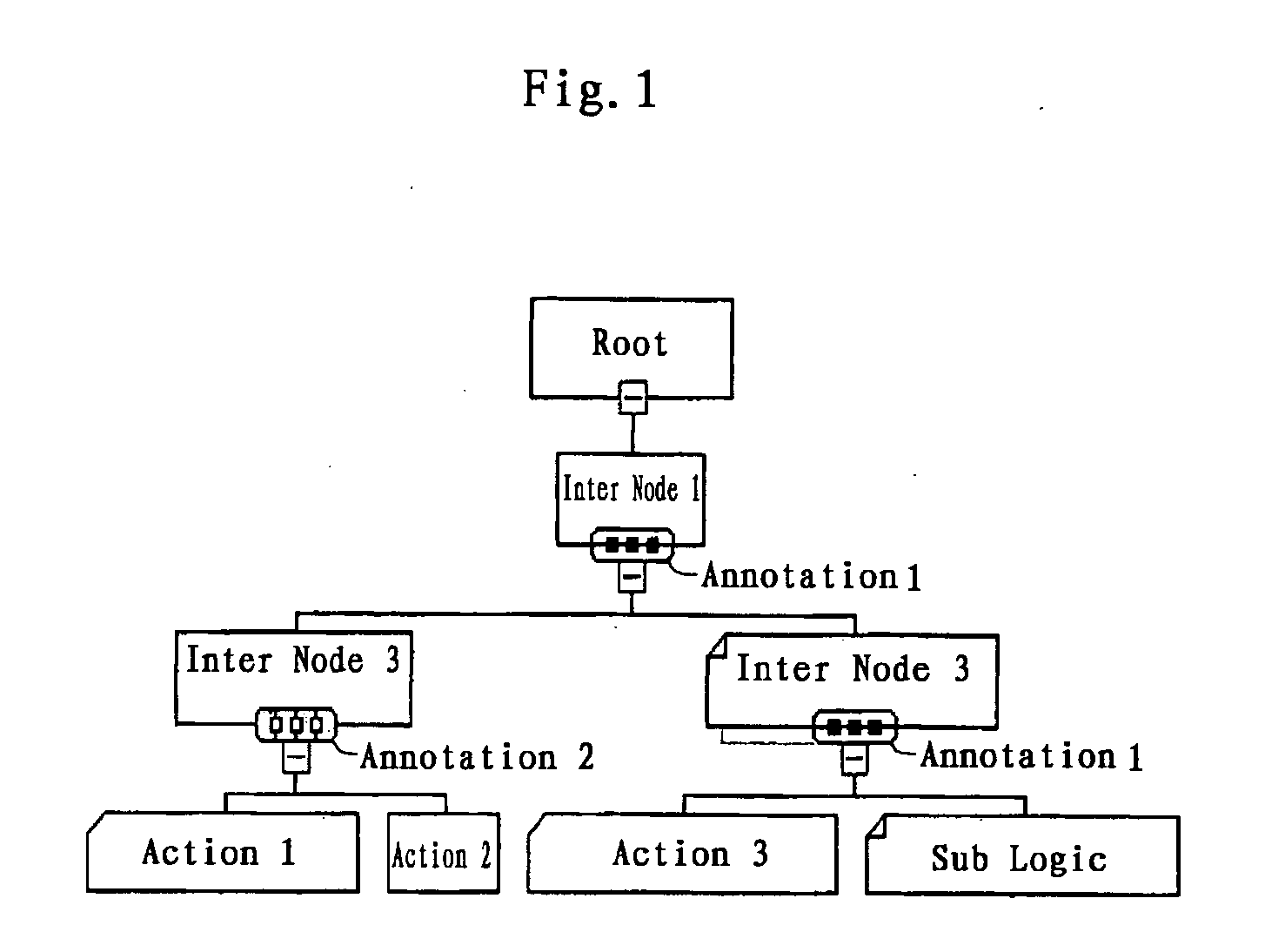
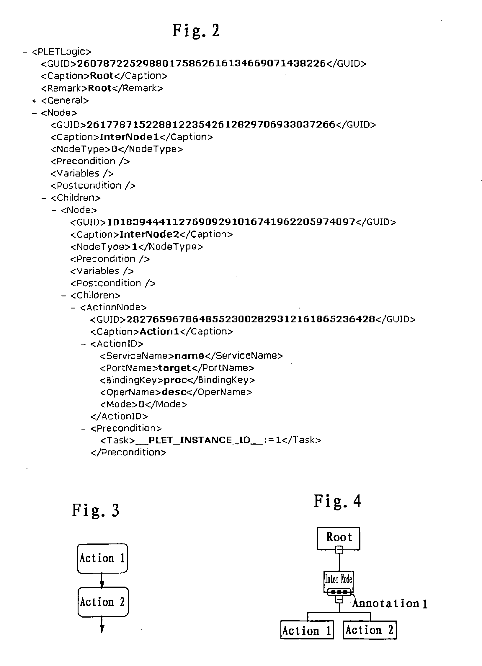
[0016] An aspect of the invention further provides a processing logic modeling apparatus that may apply the above method, for modeling a task, comprising an editor and an interpreter, for mapping the tree and the annotations into script of the processing logic, the editor comprising: a tree editor for editing a tree corresponding to a processing logic and showing how the task is decomposed into at least one level of sub-tasks, and annotation editor for editing annotations for the nodes of the tree, the annotations representing the relations between the nodes of various levels.

Problems solved by technology

However, such flow model is not easy to understand if the process is complex, especially for business analyst.
This brings big gap for process design between business operation level and IT implementation level.
A complex process is not easy to be decomposed to simple atomic processes due to the complicated relationship between entities of a flow model.
Although this application takes use of tree-style diagram to describe a detailed project plan, it is not process description initiative, so it has no capability to streamline the procedure of a process.
Although it also features a tree-style structure to describe a processing logic, it targets to describe sequence processing in the specific domain but has no enough and necessary processing logic modeling capabilities, such as parallel processing, loop and sub-logic support.

Method used


Image

  • Processing logic modeling and execution
  • Processing logic modeling and execution
  • Processing logic modeling and execution

Examples


Embodiment Construction

[0027] The present invention provides processing logic modeling and executing methods, systems and apparatus, to facilitate collaboration between business analyst and IT staff for process modeling. while maintaining the consistency between business level design and IT implementation design. To this end, the invention adopts a strategy of divide-and-conquer to decompose a task into sub-tasks and express it in form of a tree, use annotations to the nodes of the tree to represent the relations between the sub-tasks, and thus complete a processing logic. When executing the processing logic, the tree is traversed according to the annotations. The traversing includes depth-first traversing and broadness-first traversing. The executing apparatus automatically select the depth-first traversing algorithm or the broadness-first traversing algorithm according to the annotations to the nodes, and thus execute the predetermined processing logic.

[0028] Specifically, the invention provides a proc...


PUM


Abstract

Provides processing logic modeling and executing methods, systems and apparatus. These facilitate collaboration between business analyst and IT staff for process modeling and maintenance of the consistency between business level design and IT implementation design. A task is decomposed into sub-tasks and is represented by a tree. Annotations to the nodes of the tree are used to represent the relations between the sub-tasks. A processing logic is thus completed. When executing the processing logic, traversing the tree follows according to the annotations.

Description

TECHNICAL FIELD [0001] The present application generally relates to processing logic modeling and execution, especially to a processing logic modeling method, a processing logic executing method, a processing logic modeling apparatus and a processing logic executing apparatus. BACKGROUND OF THE INVENTION [0002] Processing logic represents the procedural steps to accomplish a process or a complex task. Processing logic modeling is a common requirement when describing a process in a structured way or in order to implement it on IT system. To improve the business process's visibility and flexibility for change, business and industries have striven to capture and streamline the business processes. [0003] Well known workflow system has been widely used in this field. Normally it features a directed graph based flow method to describe a structured set of activities designed to produce a specific output. However, such flow model is not easy to understand if the process is complex, especial...

Claims


Application Information

Patent Timeline
IPC IPC(8): G06F9/44G06F15/18
CPCG06F8/20
Inventor TIAN, ZHONGYE, SHENGZHANG, XINLI, JINGSUN, WEIZHANG, GUAN QUN
Owner IBM CORP
Learn More