Sphygmomanometer clamping device and electronic sphygmomanometer
a technology of sphygmomanometer and clamping device, which is applied in the field of clamping device, can solve the problems of increasing noise and current consumption, increasing the number of parts, and complicated devices, and achieves the effects of reducing the size of the clamping device, reducing the number of components, and stably applying the voltag
- Summary
- Abstract
- Description
- Claims
- Application Information
AI Technical Summary
Benefits of technology
Problems solved by technology
Method used
Image


Examples
first embodiment
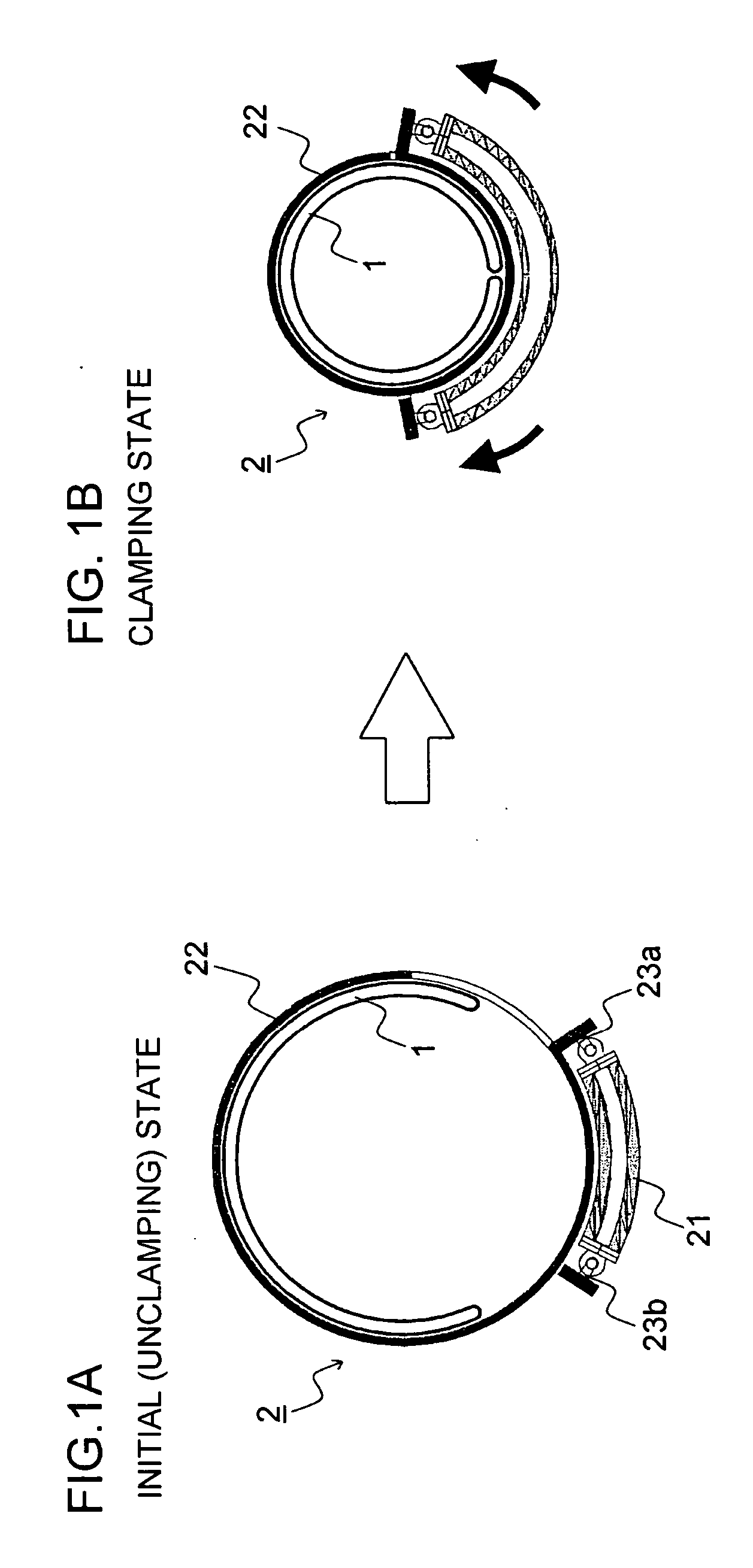
[0059]FIGS. 1A and 1B are cross-sectional views that depict a clamping operation of a clamping device according to a first embodiment. FIG. 2 is a perspective view that depicts the clamping operation of the clamping device according to the first embodiment.
[0060] The clamping device 2 shown in FIGS. 1A and 1B includes the actuator 21 that includes an EPAM which can expand or contract when a voltage is applied thereto and electrodes (not shown) for applying the voltage to the EPAM, the curler 22 that is a generally ring-shaped fixture deformed to clamp a part of the living body according to the expansion or contraction of the EPAM and serving to fixedly clamp the fluid bag 1 to the upper arm, and junction portions 23a and 23b that connect ends of the actuator 21 to the curler 22.
[0061] The fluid bag 1 is provided within the curler 22 and pressurized during the blood pressure measurement. The curler 22 clamps a part of the living body, e.g., the upper arm through the fluid bag 1.
[0...
second embodiment
[0072]FIGS. 6A and 6B are cross-sectional views that depict a clamping operation of a clamping device according to a second embodiment. FIGS. 7A and 7B are perspective views that depict the clamping operation of the clamping device according to the second embodiment.
[0073] A clamping device 102 shown in FIGS. 6A and 6B includes an actuator 121 that includes an EPAM which can expand or contract when a voltage is applied thereto and electrodes (not shown) for applying the voltage to the EPAM, a curler 122 that is a generally ring-shaped fixture deformed to clamp a part of the living body according to the expansion or contraction of the EPAM and fixedly clamping a fluid bag 101 to the upper arm, junction portions 123a and 123b that connect ends of the actuator 121 to the curler 122, and electrodes (not shown) arranged to apply the voltage to the actuator 121.
[0074] As shown in FIGS. 7A and 7B, the curler 122 is of a cylindrical shape configured so that one end of a plate-like elastic...
third embodiment
[0080]FIGS. 8A and 8B are perspective views that depict a clamping operation of a clamping device according to a third embodiment.
[0081] A clamping device 202 shown in FIGS. 8A and 8B includes a plurality of divided curlers 222, a plurality of actuators 221 contracting in an electric field direction and expanding in a direction perpendicular to the electric field direction when a voltage is applied thereto, junction portions 223a and 223b that connect ends of the actuators 221 to the respective divided curlers 222, spring portions 224 serving as expansion and contraction portions that hold an inside diameter of each curler to such an extent as to be able to insert the upper arm into the curlers 222 while no voltage is applied thereto, and electrodes (not shown) arranged on the junction portions between the actuators 221 and the divided curlers 222 to apply a voltage to the actuator 221.
[0082] Each of the divided curlers 222 includes a circular arc-shaped main body portion 222a pro...
PUM
 Abstract
Description
Claims
Application Information
 - R&D
- Intellectual Property
- Life Sciences
- Materials
- Tech Scout
- Unparalleled Data Quality
- Higher Quality Content
- 60% Fewer Hallucinations
Browse by: Latest US Patents, China's latest patents, Technical Efficacy Thesaurus, Application Domain, Technology Topic, Popular Technical Reports.
© 2025 PatSnap. All rights reserved.Legal|Privacy policy|Modern Slavery Act Transparency Statement|Sitemap|About US| Contact US: help@patsnap.com