
Combine harvester with ready adjustment of discharge positions of straw and chaff

a harvester and ready-to-use technology, applied in the direction of mowers, threshers, agriculture tools and machines, etc., can solve the problems of inability to spread chaff wide, high cost, and inability to increase the amount of chaff required, so as to reduce the cost and simplify the method

Inactive Publication Date: 2005-12-22
REDEKOP CHAFF SYST
View PDF3 Cites 54 Cited by
  • Summary
  • Abstract
  • Description
  • Claims
  • Application Information

AI Technical Summary

Benefits of technology

[0013] It is one object of the present invention to provide an improved arrangement in a combine harvester which allows a simplified and cost reduced method to spread chaff with a mechanism to utilize the straw chopper to spread the chaff when straw is being dropped
[0014] It is one object of the present invention to provide an improved arrangement in a combine harvester, which provides a simplified method to switch from full drop to full spread of both straw and chaff.
[0015] It is one object of the present invention to provide an improved arrangement in a combine harvester, which provides a simplified method to enhance the fins to spread chaff though the chopper.
[0016] It is one object of the present invention to provide an improved arrangement in a combine harvester, which provides alternate straw chopper discharge locations, thereby utilizing a straw chopper for multiple purposes.
[0059] wherein the adjustment increases the spread width of the chaff; and

Problems solved by technology

Current methods to spread chaff are costly and require additional horsepower and components, that is chaff spinners or fans to boost chaff into chopper.
Some current combines spread chaff through the straw chopper when straw is spread, however when straw is windrowed over the chopper's tailboard the fins are lowered and a wide spread of the chaff is not possible due to the orientation of the fins directing the chaff into the ground

Method used


Image

  • Combine harvester with ready adjustment of discharge positions of straw and chaff
  • Combine harvester with ready adjustment of discharge positions of straw and chaff
  • Combine harvester with ready adjustment of discharge positions of straw and chaff

Examples


Embodiment Construction

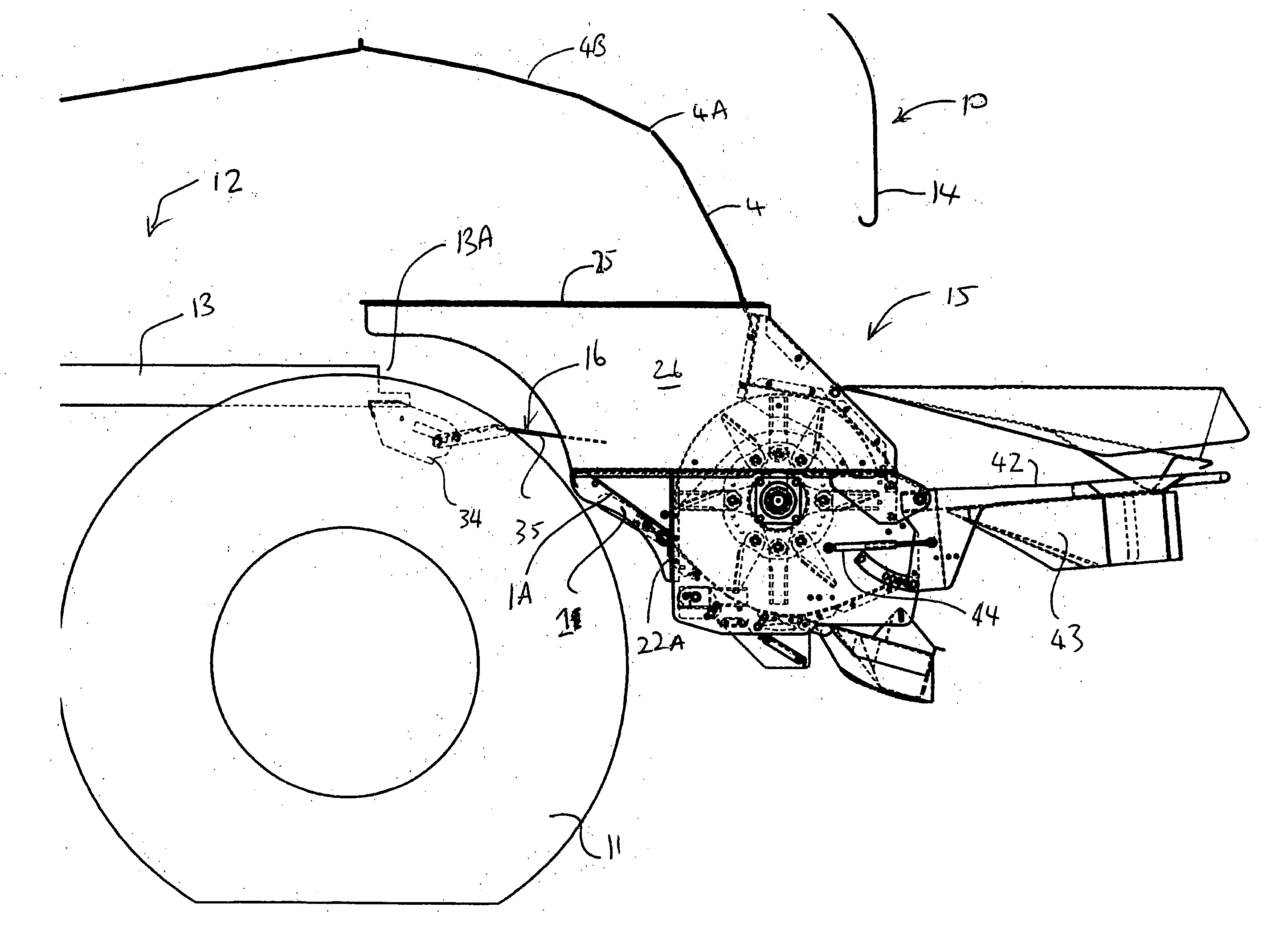
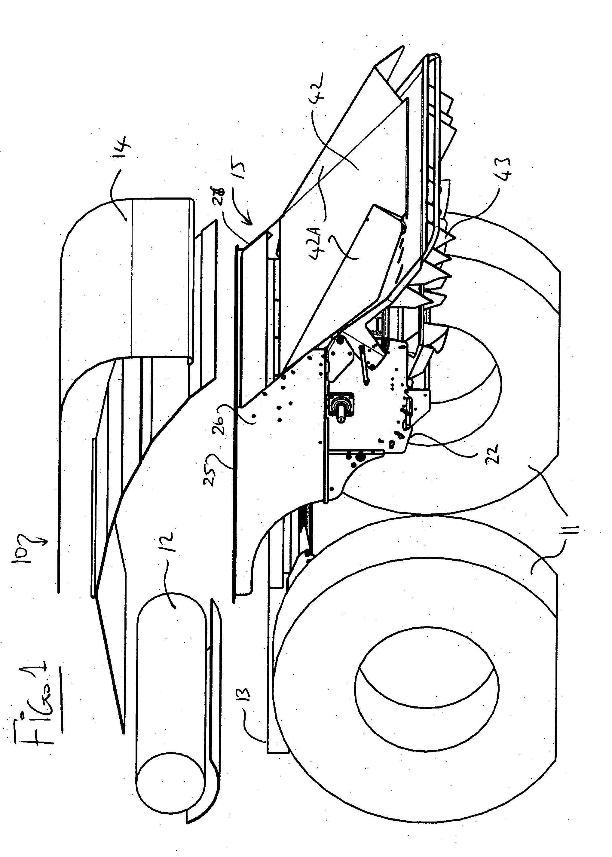
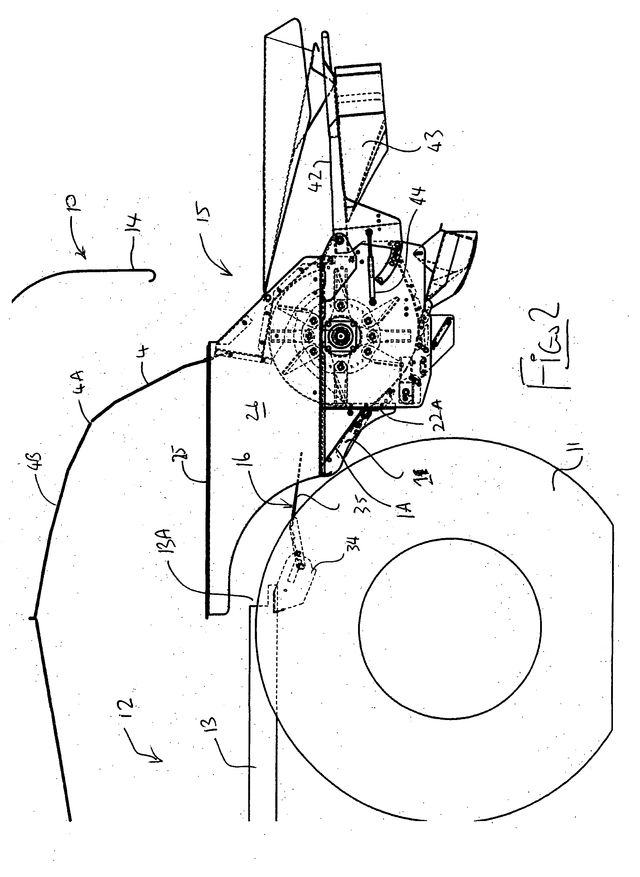
[0080] A combine harvester shown in FIGS. 1, 2 and 5 comprises a combine harvester housing 10 mounted on ground wheels 11 for transport over a ground in conventional manner. The combine harvester is shown only schematically since many different designs are available and well known to one skilled in the art. The combine harvester includes a straw separation section generally indicated at 12 and a sieve section generally indicated at 13. Again these elements are conventional and provide arrangements for separation of the straw from the crop material allowing the seed material to fall through to the sieve at which seeds are separated from the seed material leaving the chaff or other lighter materials on top of the sieve to be carried away from the sieve by an air flow through the sieve as is well known.

[0081] The rear of the combine is provided is a rear hood 14 into which air from the straw separation system and the sieves enters and into which straw is discharged rearwardly for fall...


PUM


Abstract

A combine harvester has a straw chopper attached to a rear hood behind the rear edge of the sieve assembly with a chaff guide system to bypass the chaff in front of the chopper and a straw guide system to bypass the straw above the chopper and over the tailboard. The chopper has a housing with a feed opening into which straw and / or chaff can be fed depending upon the positions of the chaff guide system and the straw guide system. A chopping assembly mounted in the housing discharges through a discharge opening through onto the tailboard having a plurality of guide fins for spreading. The housing bottom wall has a pivotal adjustment portion to allow chaff entering the feed opening and engaging the chopping assembly to discharge from the housing at a discharge position different from the discharge opening for spreading onto a supplementary spreading device.

Description

[0001] This invention relates to a combine harvester and a chopper apparatus for a combine harvester, which is readily adjustable to allow the straw and chaff to be spread or windrowed independently as required. BACKGROUND OF THE INVENTION [0002] Combine development in recent years have put greater demands on the straw choppers and chaff spreaders. The main reasons are that larger combines and wider cutting widths are creating higher flows of straw and chaff; wider cutting widths create more demanding spreading widths; reduced tilling practices have put more demand on even spreading of both straw and chaff and that plant breeding has resulted in tougher straw, higher yields and more residue. [0003] Farmers are demanding straw and chaff spreading systems that will allow them to adjust or operate the combine to select one of the following options, depending upon the requirements at that time: [0004] Spread the straw and chaff evenly over the entire cutting widths of the combine which ...

Claims


Application Information

Patent Timeline
Patent Type & Authority Applications(United States)
IPC IPC(8): A01D41/12A01D43/06A01D45/00A01D57/00A01F12/40
CPCA01F12/40A01D41/1243
Inventor REDEKOP, LEOREDEKOP, KEVINMAYERLE, DEAN
Owner REDEKOP CHAFF SYST
Learn More