Short resonant ridge waveguide load under radiation slot

a short resonant ridge waveguide and radiation slot technology, applied in slot antennas, linear waveguide fed arrays, antennas, etc., can solve problems such as unoptimized, and achieve the effect of simple and extremely effective microwave energy absorption resonant loads

Inactive Publication Date: 2005-12-22
THE UNITED STATES OF AMERICA AS REPRESENTED BY THE SECRETARY OF THE NAVY
View PDF3 Cites 4 Cited by
  • Summary
  • Abstract
  • Description
  • Claims
  • Application Information

AI Technical Summary

Problems solved by technology

While functioning adequately as an absorptive load to absorb microwave energy, the physical size of the load of U.S. Pat. No. 3,978,485 is relatively long and thus not optimal when the antenna is to be located in a confined space or there are size limitations placed on the antenna.

Method used


Image

  • Short resonant ridge waveguide load under radiation slot
  • Short resonant ridge waveguide load under radiation slot
  • Short resonant ridge waveguide load under radiation slot

Examples


Embodiment Construction

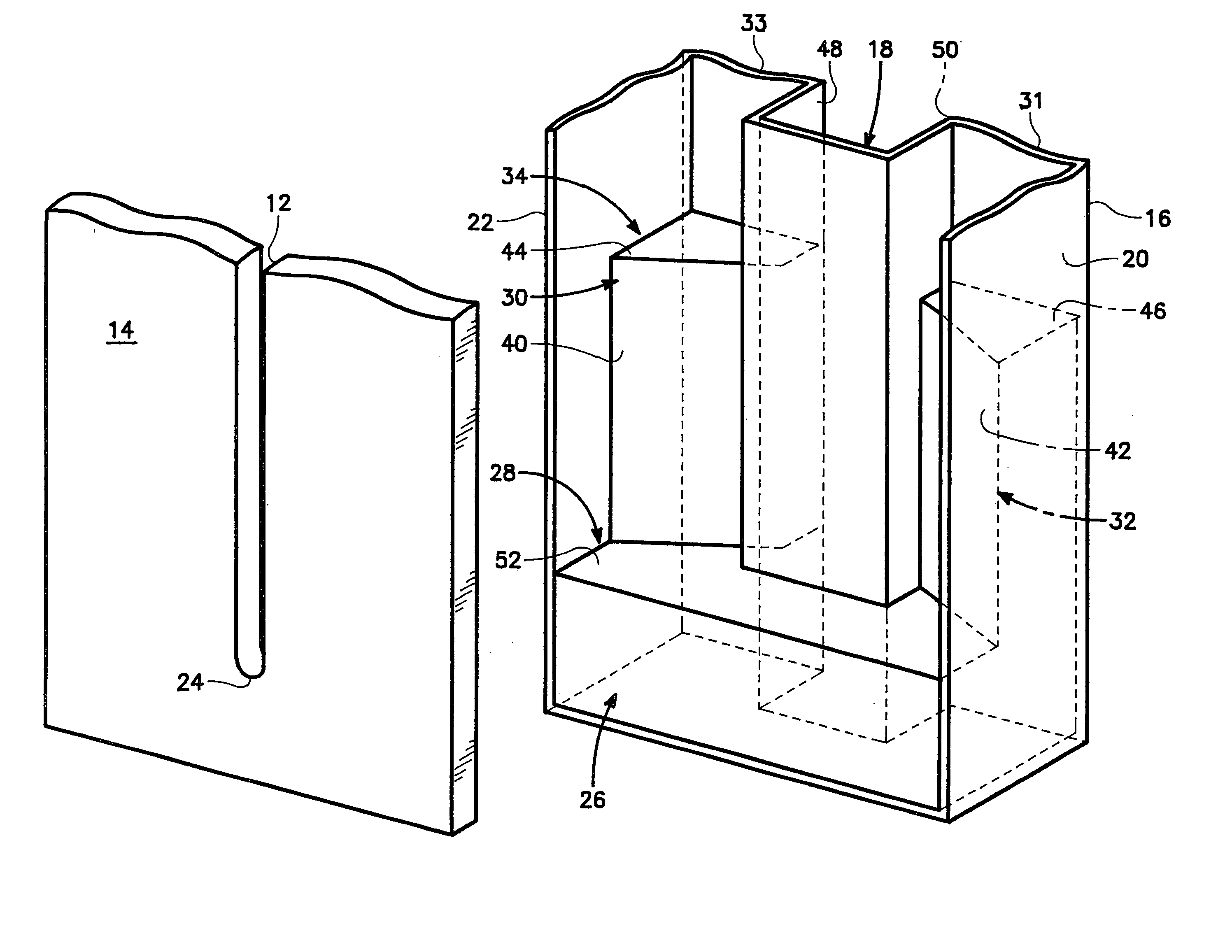
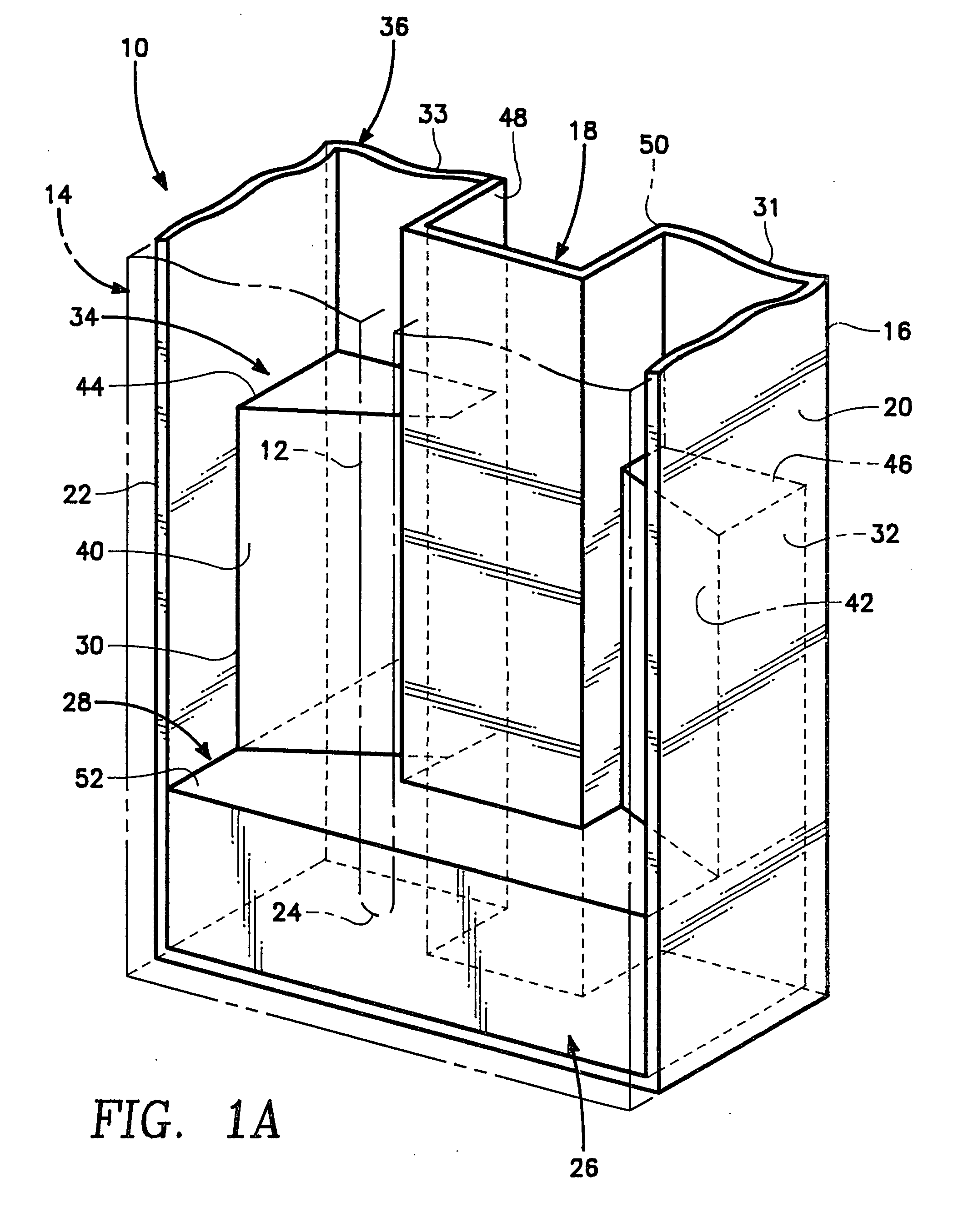
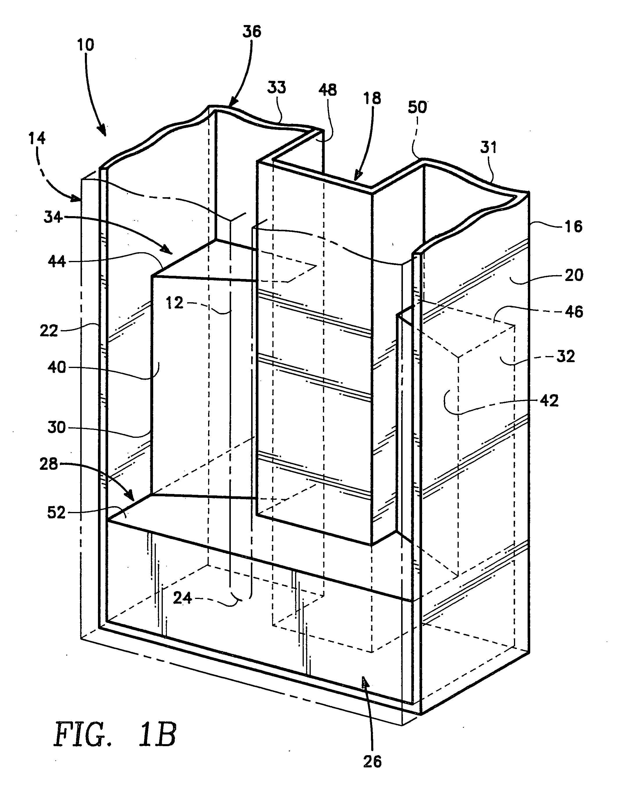
[0012] Referring to FIGS. 1A, 1B and 2, there is shown a slotted waveguide antenna 10 consisting of straight slot 12 which runs along the broad or upper face 14 of the waveguide antenna 10. The bottom or lower face 16 of waveguide antenna 10 has a ridge 18 which is generally centrally located within the lower face 16 of waveguide antenna 10, although ridge 18 can be asymmetrical. Ridge 18 runs the length of antenna 10. Waveguide antenna 10 also has a pair of sidewalls 20 and 22 which with upper face 14 and lower face 16 form a rectangular shaped ridge waveguide.

[0013] While shown as a flat surface in FIG. 1, the upper face 14 may conform to other geometries such as an upper face having a curved surface. A radome or cover may be placed over upper face 14 and slot 12

[0014] Positioned directly under the rear end 24 of slot 12 is the back section 26 of a resonant load 28. Extending forward from the back section 26 of resonant load 28 are a pair of angled posts or teeth 30 and 32 which ...


PUM


Abstract

A short ridge waveguide load is described which absorbs and cancels non-radiated electromagnetic energy in continuous slot or discrete slotted antennas. The load achieves a small physical size by using a resonant structure which includes an absorbing ferrite front section positioned within the interior of the waveguide antenna below the slot and a back section of ferrite material also positioned in the interior of the waveguide antenna. This allows for energy to be radiated from the slot while absorbing and canceling the non-radiated energy using a relatively small size load. In a rectangular ridge waveguide configuration, the front section consists of a pair of posts having a trapezoidal, rectangular or triangular shape.

Description

BACKGROUND OF THE INVENTION [0001] 1. Field of the Invention [0002] The present invention relates generally to ridge waveguide antenna loads and often, more particularly, to traveling wave antennas, such as a continuous slot or discrete slotted ridge waveguide antenna which includes a load positioned at the end of the antenna to absorb and cancel the non-radiated energy. [0003] 2. Description of the Prior Art [0004] In the past, slotted antennas generally included tapered loads or resonant loads positioned behind the antenna's radiating slot or at the end of the slot. For example, U.S. Pat. No. 3,978,485 to Pierre Bonnaval, which issued Aug. 31, 1976, illustrates a continuous slot antenna having a waveguide closed at one end with a tapered load positioned at the closed end of the waveguide to absorb non-radiated energy. While functioning adequately as an absorptive load to absorb microwave energy, the physical size of the load of U.S. Pat. No. 3,978,485 is relatively long and thus n...

Claims


Application Information

Patent Timeline
Patent Type & Authority Applications(United States)
IPC IPC(8): H01P1/26H01Q13/00H01Q13/10H01Q21/00
CPCH01P1/264H01Q21/005H01Q21/0043H01Q13/10
Inventor CHEW, RICHARD F.FREEMAN, WILL
Owner THE UNITED STATES OF AMERICA AS REPRESENTED BY THE SECRETARY OF THE NAVY
Why Eureka
Try Eureka