Eureka AIR delivers breakthrough ideas for toughest innovation challenges, trusted by R&D personnel around the world.

Comfort product

a technology for comfort products and products, applied in the field of comfort products, can solve the problems of people being either too warm or too cold, inconveniences of being temporary, and the heat brought to the bed slowly dissipates

Inactive Publication Date: 2005-12-22
RIVERPARK INC A IN THE STATE OF INDIANA
View PDF45 Cites 167 Cited by
  • Summary
  • Abstract
  • Description
  • Claims
  • Application Information

AI Technical Summary

Benefits of technology

[0006] It is an object of the present invention to provide an improved comfort product that uses an airflow through the comfort product and which has none of the limitations of the prior art described above. It is a further object of the present invention to provide an improved comfort product that uses an airflow through a heat exchanger and into and through the comfort product to selectively heat or cool an occupant of the comfort product and which has non of the limitations of the prior art described above.

Problems solved by technology

For as long as people have been sleeping in beds there have been problems with people being either too warm or too cold while in the bed.
These practices have the inconveniences of being temporary (in that the heat brought to bed slowly dissipates) and time consuming (in that considerable preparation must occur).
Plus neither of these methods actually cool the bed—they only provide heat.
One disadvantage is it is expensive and inefficient to heat or cool areas that are not occupied (such as areas outside of the bed during sleep) when the person really just wants their immediate area—the bed—to be comfortable.
Another disadvantage is the bed itself can sometimes be warmer or colder than the surrounding air, to the discomfort of the person sleeping.
Yet another disadvantage is warming or cooling the entire enclosure may not be feasible if the bed is not in a building; e.g. if it is in a recreational vehicle or in the sleeping compartment of a semi-truck.
These earlier inventions were often cumbersome and complicated which made them expensive to produce and use.
While less complicated than the previous inventions, this mattress still relies upon the structure of a traditional inner-spring mattress making it expensive and therefore unsuitable for use outside of the home or for a lower cost application such as a pet bed.
The modular ventilated bed disclosed in U.S. Pat. No. 4,665,575 shows a bed designed for use outside of a home, but it does not include forced air for heating or cooling which limits its effectiveness at transferring heat to or from the occupant.
This limits the usefulness of the invention much the same way as the old heating bricks or hot water bottles did since the ice-packs will melt or the heating packs will cool and the cooling or heating will end.

Method used


Image

  • Comfort product
  • Comfort product
  • Comfort product

Examples


Embodiment Construction

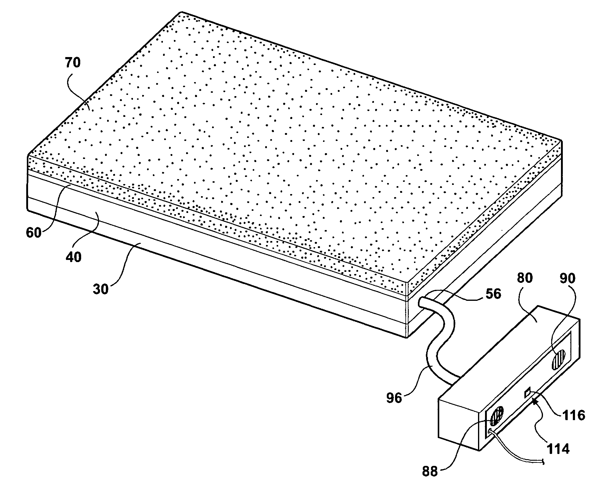
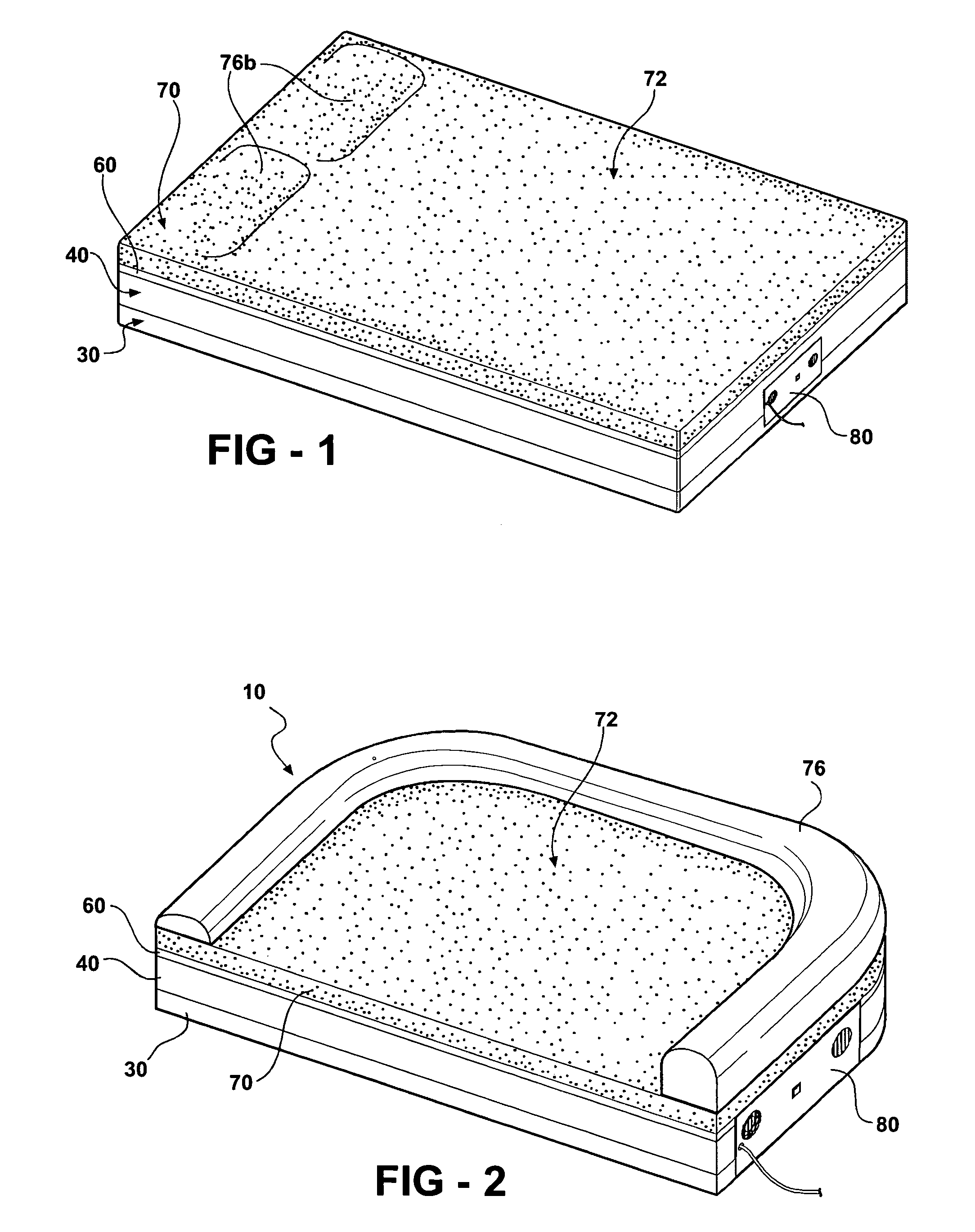
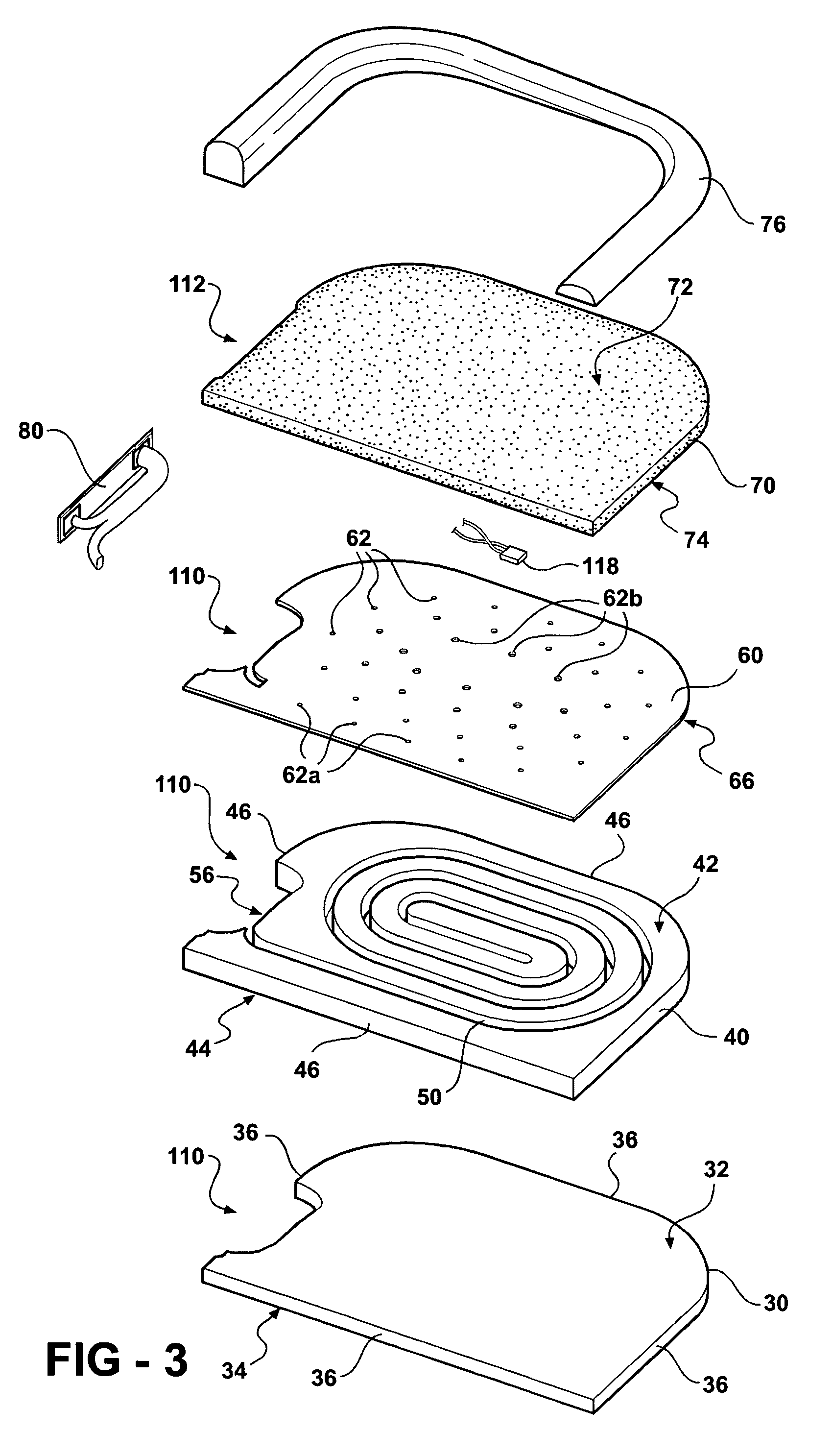
[0028] The following descriptions are of exemplary embodiments only, and are not intended to limit the scope, application of configuration of the invention in any way. Rather, the following descriptions provide a convenient illustration for implementing exemplary embodiments of the invention. Various changes to the described embodiments may be made in the function and arrangement of the elements described without departing from the scope of the invention as set for in the claims. Referring to FIGS. 1, there is shown an improved structure of a comfort product 10 having means to distribute temperature conditioned air 20 through the comfort product 10. The comfort product 10 has a support layer 30, a channel layer 40, an engineered distribution layer 60 and a comfort layer 70. In addition the comfort product 10 has a heat exchanger assembly 80 to selectively heat or cool air 20 and to provide this selectively heated or cooled air 20 to the comfort product 10.

[0029] The support layer 3...


PUM


Abstract

An improved comfort product that uses an airflow through a heat exchanger and into the comfort product to selectively heat or cool an occupant has a support layer contacting and supporting a channel layer. The channel layer has at least one channel with an opening to accept air. The channel layer contacts and supports an engineered distribution layer that has numerous small holes making it air permeable. The engineered distribution layer contacts and supports an air permeable comfort layer that is of such size and shape to support an occupant of the comfort product. The comfort product also has a heat exchanger assembly for supplying heated or cooled air to the opening in the channel. The heat exchanger assembly includes an air intake having an intake fan, an exhaust outlet and a heat exchanger for selectively heating or cooling air flowing through the heat exchanger resulting in selectively heated or cooled supply air and exhaust air. The intake fan forces air through the heat exchanger where some of the air is selectively heated or cooled to be supplied to the comfort product and some air is used as exhaust air (to remove the unwanted heat if the supplied air is cooled or to warm the exhaust side of the heat exchanger if the supply air is warmed.). The selectively heated or cooled supply air then moves through the channels in the channel layer and the exhaust air exits through the exhaust vent. The selectively heated or cooled supply air then moves through the engineered distribution layer where the numerous small holes diffuse the air and then the selectively heated or cooled air then moves through the comfort layer where the air is further diffused and where the selectively heated or cooled air can selectively heat or cool an occupant of the comfort product.

Description

FIELD OF THE INVENTION [0001] The present invention relates to comfort products and more particularly to comfort products in which an airflow is produced through the comfort product. The comfort product can include a heat exchanger through which the air is forced to selectively heat or cool an occupant of the comfort product. Applications of the invention include beds for pets and human occupants. BACKGROUND OF THE INVENTION [0002] For as long as people have been sleeping in beds there have been problems with people being either too warm or too cold while in the bed. In the past people would warm bricks in the fireplace and insert these bricks under the sheets or even the mattress to warm the bed before entering. As the industrial revolution made consumer products more affordable this practice gave way to people taking hot water bottles to bed with them for the same purpose. These practices have the inconveniences of being temporary (in that the heat brought to bed slowly dissipates...

Claims


Application Information

Patent Timeline
Patent Type & Authority Applications(United States)
IPC IPC(8): A47C21/04A47C27/00
CPCA01K1/0353A47C21/048A47C21/044
Inventor BAHASH, LISA JANELIPSKI, MICHAEL RAYMOND
Owner RIVERPARK INC A IN THE STATE OF INDIANA
Why Eureka
Eureka Blog
Learn More