
Method and apparatus for reducing drip from spray nozzles

a technology of spray nozzles and spray nozzles, which is applied in the field of methods and, can solve the problems of significantly higher cost of incorporating and maintaining such a system than the conventional boom valve, and achieve the effects of reducing time, reducing pressure of trapped air, and reducing volume of compressed air

Inactive Publication Date: 2005-12-08
BRANDT IND
View PDF1 Cites 4 Cited by
  • Summary
  • Abstract
  • Description
  • Claims
  • Application Information

AI Technical Summary

Benefits of technology

"The present invention provides a spraying method and apparatus that overcomes problems in prior art spraying systems. The invention reduces the amount of air in the conduit carrying liquid to a spray nozzle, by drawing liquid from an upper portion of the supply conduit and reducing the volume of air trapped in the conduit. This reduces the amount of air that needs to escape when the liquid level reaches the upper portion of the supply conduit, resulting in less liquid dripping from the nozzle. The invention also reduces the amount of air in the supply conduit by venting air from the supply conduit when pressurized liquid is directed into the supply conduit. The method and apparatus of the invention provide improved spraying efficiency and reduced air drip, resulting in reduced costs and improved safety."

Problems solved by technology

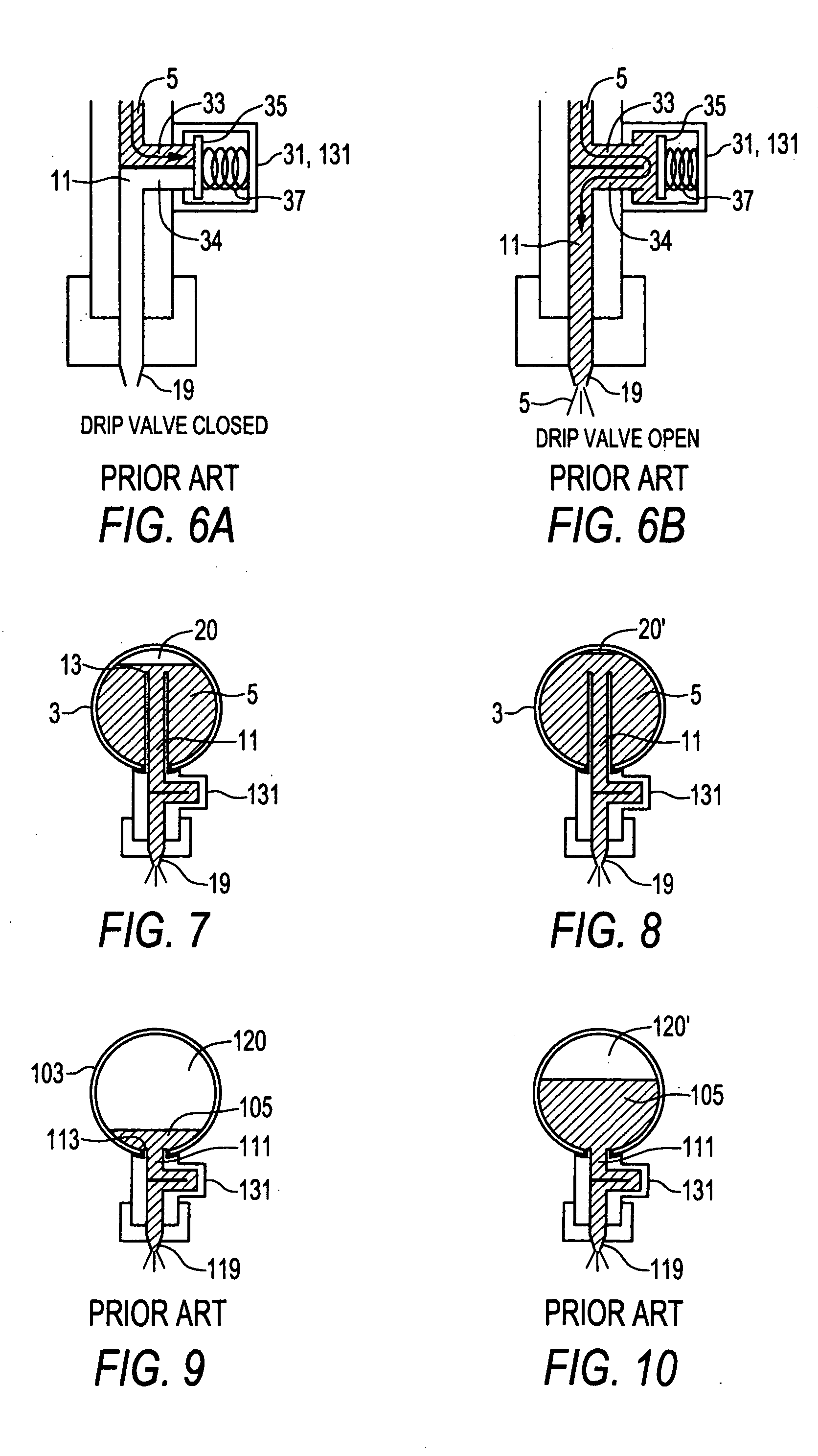
A problem with current drip valves is that they are set at an opening pressure that is significantly below the typical operating pressures.
Setting the opening pressure at a level closer to the typical operating pressure is problematic, because in some situations low pressure spraying is desired, and would not be possible if the opening pressure of the drip valves was higher than the desired low operating pressure.
Such individual nozzle valves overcome the dripping problem of conventional nozzles by providing substantially instant spray on and spray off, however the cost for incorporating and maintaining such a system is significantly higher than the conventional boom valve.

Method used


Image

  • Method and apparatus for reducing drip from spray nozzles
  • Method and apparatus for reducing drip from spray nozzles
  • Method and apparatus for reducing drip from spray nozzles

Examples


Embodiment Construction

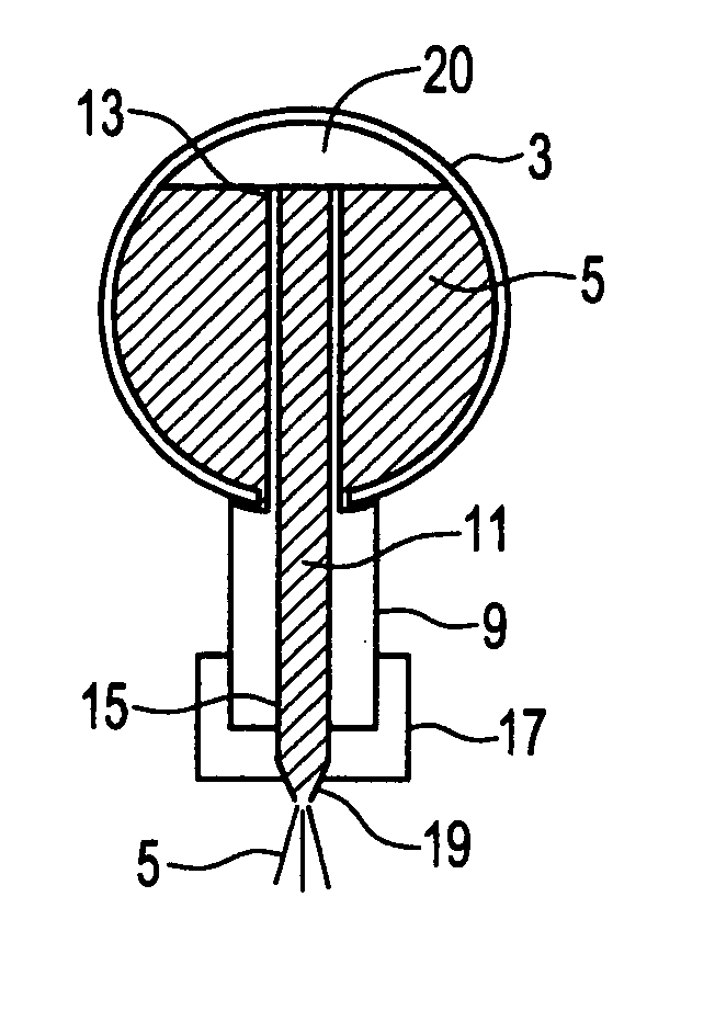
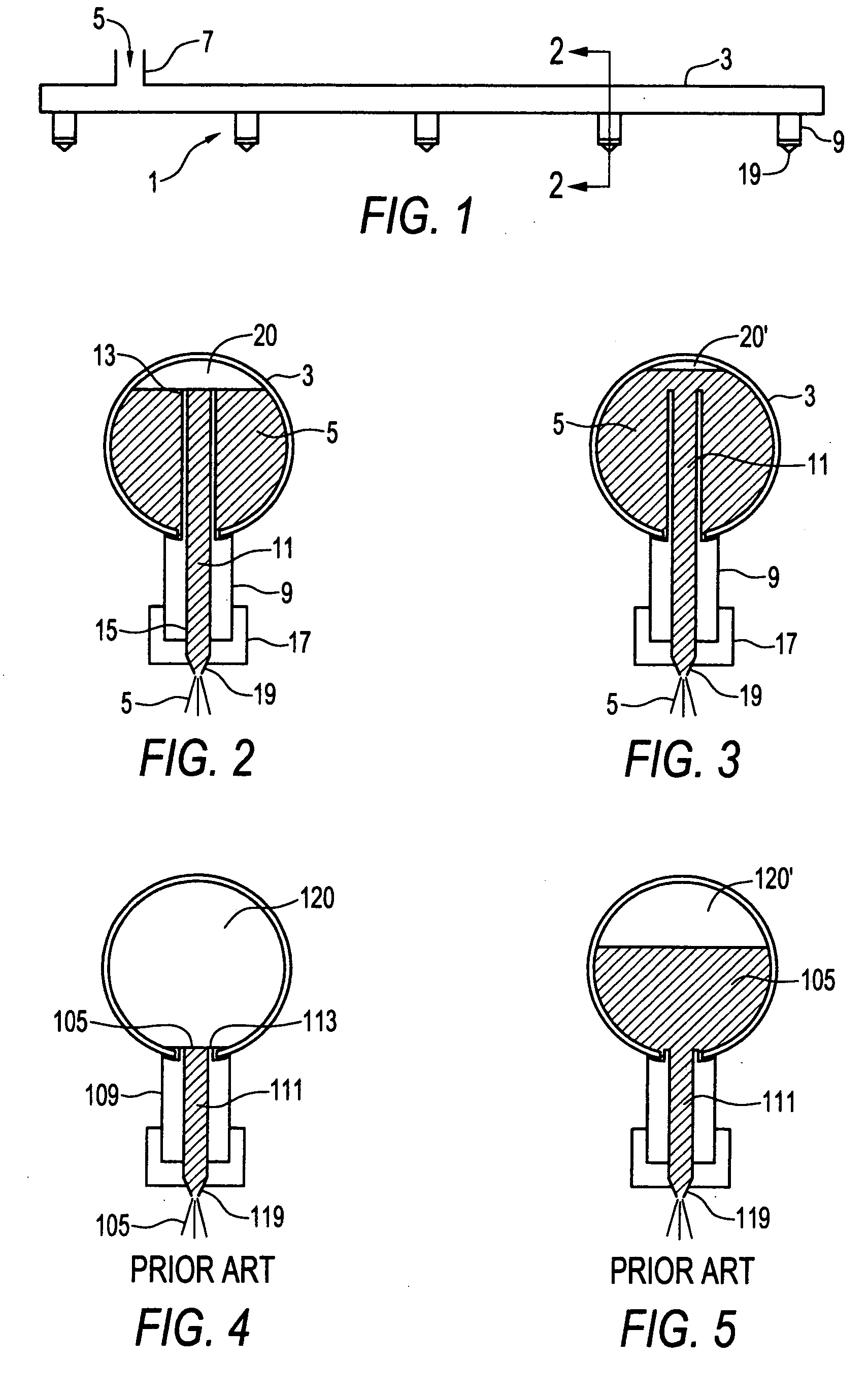
[0031]FIGS. 1-3 schematically illustrate a spraying apparatus 1 of the invention. The apparatus 1 comprises a generally horizontally oriented supply conduit 3 carrying pressurized liquid 5 that is pumped into the supply conduit through the inlet 7 from a pump or like pressurized liquid source. A nozzle body 9 is attached to the supply conduit 3 over an aperture through the supply conduit 3 by clamps, by screwing into a threaded aperture in the supply conduit 3, or like means as are well known in the art such that the nozzle body 9 is in sealed communication with the supply conduit 3.

[0032] A nozzle conduit 11 extends through the nozzle body 9. The nozzle conduit 9 has an input end 13 located inside the supply conduit 3 in an upper portion of the supply conduit 3 as illustrated in FIGS. 2 and 3, and an output end 15 at a lower end 17 of the nozzle body 9. A nozzle 19 is secured in a lower end 17 of the nozzle body 9 at the output end 15 of the nozzle conduit 11 such that pressurized...


PUM


Abstract

A method of reducing drip from a nozzle mounted to a generally horizontally oriented supply conduit comprises reducing the amount of air remaining in the supply conduit when the nozzles are spraying liquid. Conveniently the amount of air remaining in the supply conduit can be reduced by drawing liquid from an upper portion of the supply conduit to supply the nozzle. An apparatus for practicing the method comprises a nozzle secured at the output end of a nozzle conduit wherein the input end of the nozzle conduit is located in an upper portion of the supply conduit.

Description

[0001] This application claims priority benefit of Canadian Patent Application Serial No. ______, filed May 11, 2004. [0002] This invention is in the field of equipment for spraying, and in particular such equipment wherein one or more nozzles are connected to a hollow supply conduit to receive liquid to be dispensed from the nozzle. BACKGROUND OF THE INVENTION [0003] Spraying equipment in agriculture, construction, and other industries is used for spraying various liquids on surfaces, commonly ground surfaces. In order to cover a wide swath of ground, sprayers typically comprise a substantially horizontal boom with nozzles mounted thereon that are fed from a supply via a conduit. Agricultural sprayers, for example, are typically either wet boom or dry boom sprayers. In a wet boom sprayer, the horizontal boom is a rigid hollow pipe with the nozzles mounted directly to the pipe, and the pipe performs the function of the conduit. In a dry boom sprayer, the horizontal boom is a rigid b...

Claims


Application Information

Patent Timeline
Patent Type & Authority Applications(United States)
IPC IPC(8): B05B1/20B05B1/28B05B15/06
CPCB05B1/202B05B15/069B05B1/28B05B15/658
Inventor BODIE, CAMERON DWIGHT
Owner BRANDT IND
Learn More