Model 1911 type firearm safety lock

a safety lock and pistol technology, applied in the field of pistols, to achieve the effect of effective means of locking down a firearm and easy replacemen

Inactive Publication Date: 2005-12-08
SPRINGFIELD INC
View PDF57 Cites 18 Cited by
  • Summary
  • Abstract
  • Description
  • Claims
  • Application Information

AI Technical Summary

Benefits of technology

[0007] The disclosed invention relates to an internally operated safety device or safety lock designed to prevent firing of a Colt government model 1911 style semiautomatic pistol. The invention operates by selectively arresting the movement of the buffer device which sits atop the trigger spring contained within the pistol grip of the gun. The present invention provides a means to retrofit existing 1911 style semiautomatic handguns with the device without permanently altering or damaging the firearm. By utilizing existing internal components, and providing a modification of certain components which are easily replaceable, the disclosed invention provides for an effective means to lock down a firearm by replacement of certain modified parts. However, the firearm may be restored to its original condition by replacement of conventional, inexpensive parts, thereby allowing an owner of the firearm to install the safety device without any apprehension about destroying the value of the gun or permanently altering the major components of the firearm.
[0008] The invention operates by arresting or preventing the upward or downward travel of a spring buffer device which is located at the interface of an operating rod which connects the hammer mechanism with the main spring. The main spring provides the potential energy or spring bias, for the return of the hammer upon the activation of the trigger once the hammer has been cocked. The invention suggests a means to lock the firearm utilizing a simple screw type device. A more elaborate locking mechanism may be used to prevent removal of the locking device once engaged in the safe position. Such locking mechanisms form a basis for a key style firearm lock which is internal to the firearm.

Problems solved by technology

Such manual safeties are positioned to allow their manipulation by the shooter, but are generally not designed to have a lock on device which will prevent the activation of the pistol by an unauthorized user.

Method used


Image

  • Model 1911 type firearm safety lock
  • Model 1911 type firearm safety lock
  • Model 1911 type firearm safety lock

Examples


Embodiment Construction

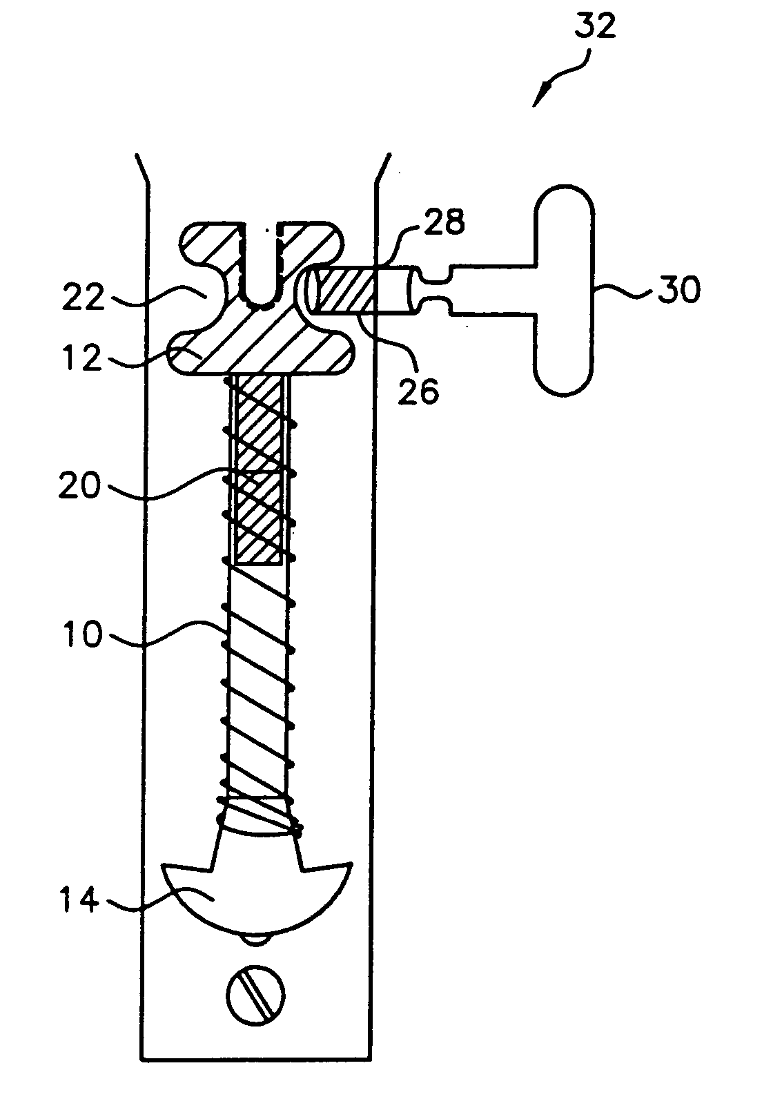
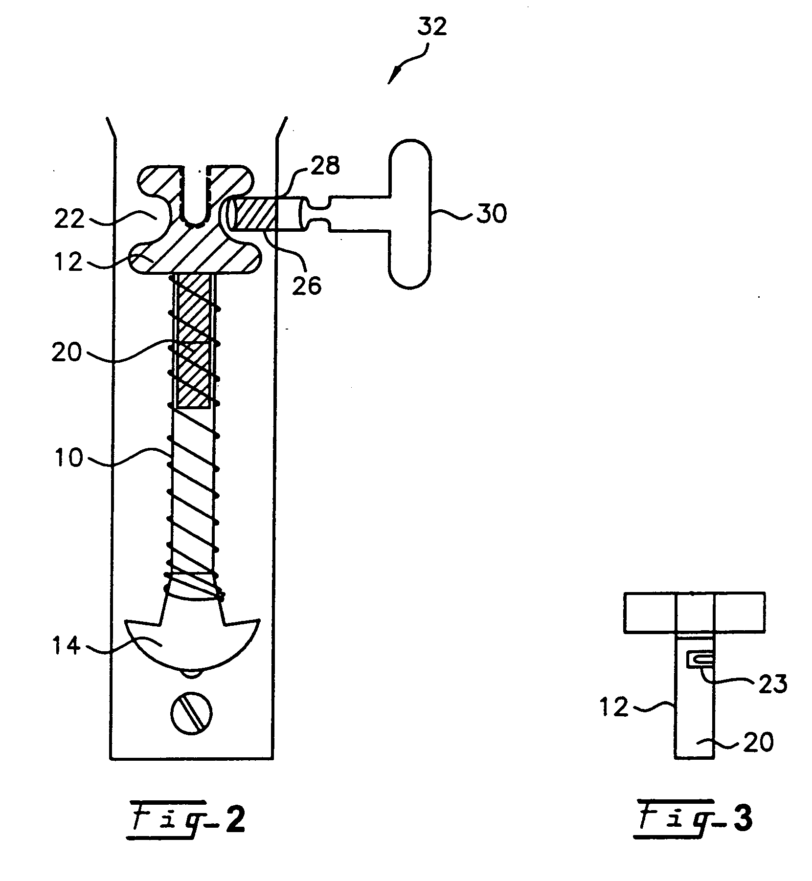
[0012] The invention will now be described with reference to the various figures in which like numbers refer to like parts for a typical model 1911 style handgun. Turing to FIG. 1, an exploded view of the pistol is seen utilizing parts which will seem familiar to gunsmiths and those skilled in the art. Turning to area 38 shown on FIG. 1, it will be appreciated by those familiar with firearms that a 1911 model semiautomatic handgun utilizes a main spring contained within the pistol grip area of the handgun. The hammer 8 is attached to the trigger spring operating rod 18. FIG. 1 discloses the operating rod separately in the exploded view, through it would be appreciated by those skilled in this art that rod 18 sits within an upper notch area of buffer 12 when the pistol is assembled. Upon cocking of the hammer 8, rod 18 presents force in the downward position and urges buffer 12, sitting within the coil of the spring 10, to compress or bias the spring. The compressed spring provides t...


PUM


Abstract

A firearm safety lock for an automatic pistol such as the Model 1911 firearm is disclosed. The safety lock includes a means of arresting the operation of the main trigger or hammer spring in the pistol grip of the firearm to prevent movement of the hammer, thereby locking the gun in a safe condition. A means and a method is disclosed for locking a pistol in a sale condition by arresting the movement of the hammer spring buffer through insertion of a locking shaft through the pistol grip housing which can be keyed to prevent unauthorized removal of the locking shaft. The disclosed invention may be used on newly manufactured firearms or provides a method to easily convert an existing firearm without permanent modification or damage to the firearm.

Description

[0001] This U.S. Patent Application is a continuation of pending U.S. patent application Ser. No. 10 / 684,902 filed on Oct. 14, 2003, which is a continuation of U.S. patent application Ser. No. 09 / 837,922 (now U.S. Pat. No. 6,647,655) filed on Apr. 18, 2001, which claimed the benefit of U.S. Provisional Patent Application Ser. No. 60 / 263,906, filed Jan. 24, 2001 and of U.S. Provisional Patent Application No. 60 / 198,525, filed Apr. 19, 2000. This application also claims the benefit of the provisional patent applications cited immediately above.BACKGROUND OF THE INVENTION [0002] The present invention relates to firearms, such as pistols, which use hammers which fire the pistol upon activation of a trigger mechanism. The disclosed invention will operate with such pistols which use a main spring or trigger spring which activates the movement of the hammer to fire the pistol. The disclosed safety lock device will work on any pistol design similar to the well-known 1911 style government pi...

Claims


Application Information

Patent Timeline
Patent Type & Authority Applications(United States)
IPC IPC(8): F41A17/00F41A17/74
CPCY10T29/49716F41A17/74
Inventor SALVITTI, ALFRED W.
Owner SPRINGFIELD INC
Why Eureka
Try Eureka