
Handle for forceps/tweezers and method and apparatus for designing the like

a technology of hand and tweezers, applied in the direction of surgical forceps, mechanical control devices, incision instruments, etc., can solve the problems of hand strain, muscle and joint strain, and the chance of fatigue and strain in these muscles and their fascicles is greater

Inactive Publication Date: 2005-12-01
TILLIM STEPHEN L
View PDF99 Cites 14 Cited by
  • Summary
  • Abstract
  • Description
  • Claims
  • Application Information

AI Technical Summary

Benefits of technology

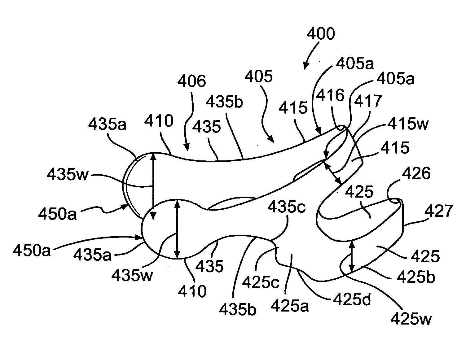
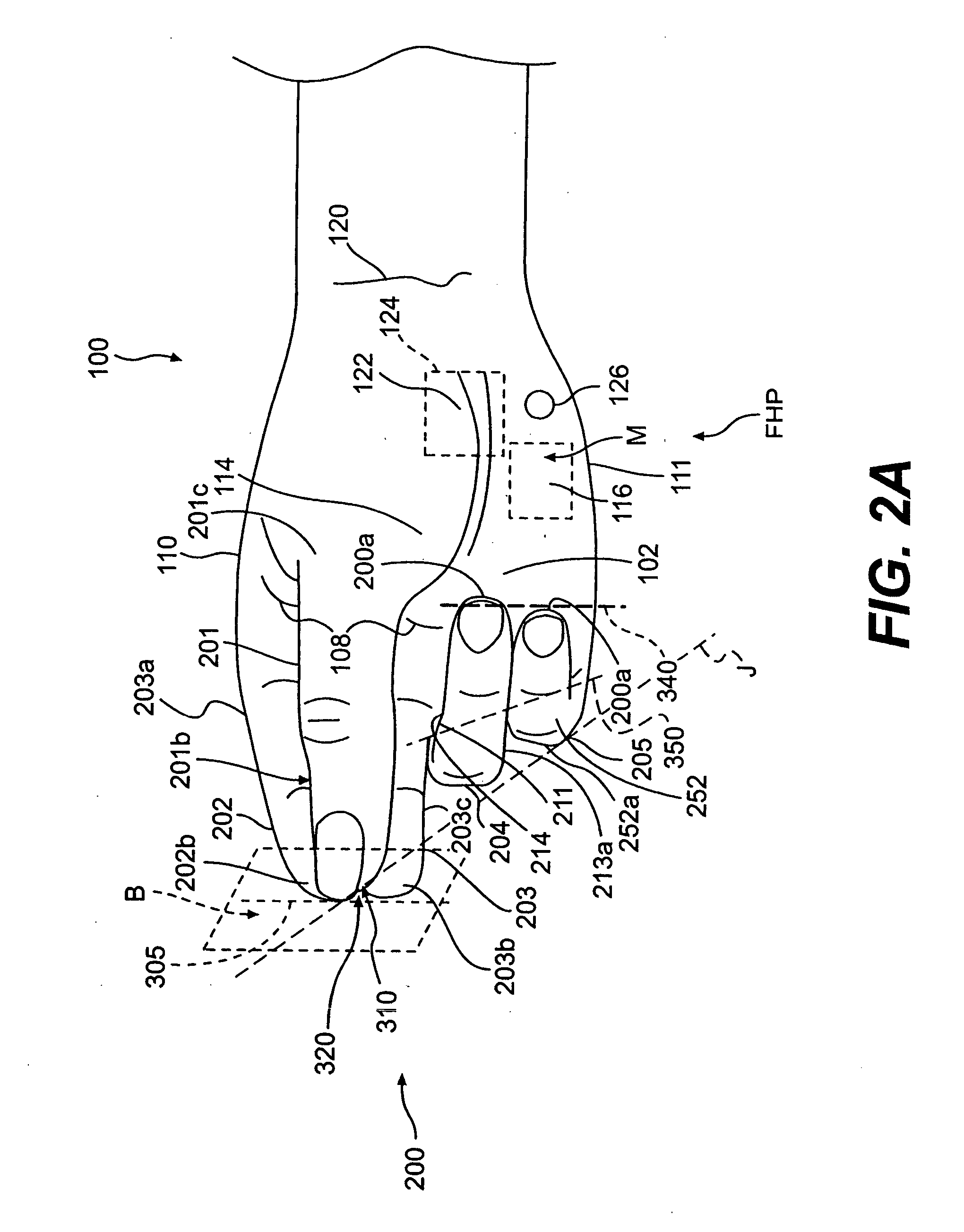
"The present invention provides handles for forceps / tweezers that are designed to improve efficiency and comfort for the user. The handles are based on the anatomy of the hand and the natural position of the fingers when pinching or using the forceps. The design method and apparatus use lines and measurements from the hand to create a functional and comfortable handle. The handles reduce strain and pressure on the tendons, bursa, joints, and muscles of the hand, reducing the risk of injury and chronic irritation. The design also allows for a larger part of the hand to contact the handle, providing better grip and comfort. The handles can be of various sizes and shapes for different applications. Overall, the design improves the performance and comfort of forceps / tweezers."

Problems solved by technology

This can cause muscle and joint strain.
If fewer muscle fascicles and fibers are used to pinch, than potentially available, there is a greater chance of fatigue and strain in these muscles and their fascicles.
Additionally, hand strain can occur while using a common forceps or tweezers.
This is because the thumb and index finger have a natural tendency to advance toward the tip of the common forceps or tweezers when holding a stylus-type tool, having the potential for excessive squeezing of the forceps or tweezers.
Maintaining this awkward position can also strain finger and wrist joints and ligaments, especially when they suffer pre-existing damage.
Such awkward but common position of exaggerated flexion results from the forearm muscles and tendons contracting the middle phalange of the index finger and distal phalange of the thumb.
Thus, the strain and pressure in the CT from the tendons of the contracted superficial flexor forearm muscles resulting from such awkward position can lead to median nerve irritation and carpal tunnel syndrome (CTS).
Furthermore, strain in the muscles in the hand and forearm and can cause repetitive strain syndrome of the involved muscles.
A typical problem posed with common forceps and tweezers is that frequent use can cause pain in the hand, wrist and forearm and lead to CTS.
This problem has not been solved because the common forceps or tweezers generally adapts a stylus-type tool to pinch small objects.
Such stylus-type tools can force the hand into an uncomfortable position with the hand compensating for exaggerated finger flexion, as discussed above, leading to this problem.
The problem with many of the above examples of common forceps or tweezers is that their design and operation does not take advantage of the greater pinch strength available from opposing the thumb to the index finger and middle finger instead of opposing the thumb to the index finger.
Furthermore, the above styles of handles for common forceps or tweezers do not efficiently utilize the palm of the hand to support the handle.
In addition, the handles for common forceps and tweezers do not eficiently utilize the ring finger and small finger to hold and stabilize the handle of the forceps and tweezers.

Method used


Image

  • Handle for forceps/tweezers and method and apparatus for designing the like
  • Handle for forceps/tweezers and method and apparatus for designing the like
  • Handle for forceps/tweezers and method and apparatus for designing the like

Examples


Embodiment Construction

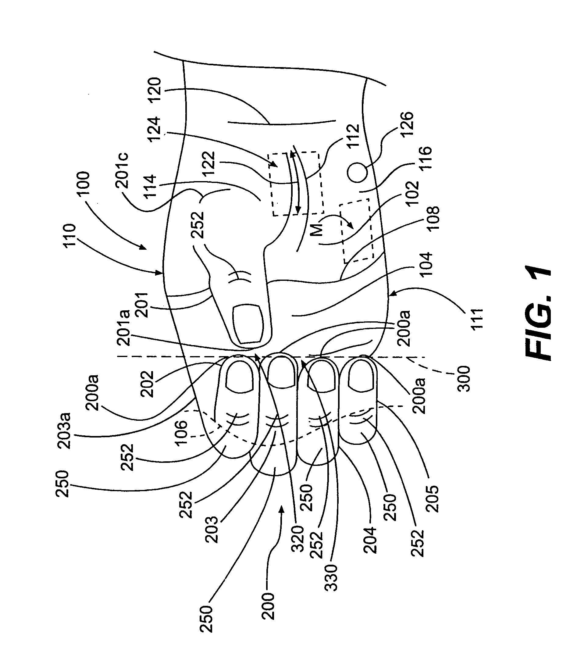
[0079] In order to more clearly and concisely describe the subject matter of the present invention, the following definition for the T Position is intended to provide guidance as to the meanings of specific terms used in the following written description. In addition, it is to be understood that the phraseology or terminology employed herein is for the purpose of description and not to be construed in a limiting sense. The following discussion relates to areas of the hand in relation to the present invention with reference to FIG. 1.

T Position

[0080]FIG. 1 illustrates the hand 100 to the T Position. The T Position is the position the hand 100 assumes when the tips 200a of the long fingers 200 are aligned and the tip 201a of the thumb 201 opposes the space 320 between the index finger 202 and middle finger 203. In this position the area that crosses the palm 102 of the hand 100 known as the palmar arch 104 is concave. The finger cup 106, shown as a dotted line, is the concave area ...


PUM


Abstract

The present invention provides a design method and apparatus for a handle providing a shape and structure that fills various regions of the hand except a region in an area over the underlying carpal tunnel. Such design method and apparatus provides for various handles for use by a hand. In particular, the apparatus includes a generally Y-shaped configuration, such as for a forceps / tweezers handle with a working end. The handle can include a radial section an ulnar section and middle section. The handle also can have a radial arm, an ulnar arm and distal leg, with an ulnar end and a radial end for engaging a portion of the hand.

Description

CLAIM FOR PRIORITY [0001] This application claims the benefit of and is a Continuation-In-Part of U.S. application Ser. No. 10 / 279,111 filed on Oct. 24, 2002, the entire disclosure of which is incorporated herein by reference; this application also claims the benefit of and is a Continuation-In-Part of International Application No. PCT / US02 / 33956, filed on Oct. 24, 2002, presently believed not to be published in English under PCT Article 21(2), the entire disclosure of which is incorporated herein by reference; and this application further claims the benefit of U.S. Provisional Patent Application Ser. No. 60 / 330,527 filed on Oct. 24, 2001, the entire disclosure of which is incorporated herein by reference.FIELD OF INVENTION [0002] The present invention provides handles for forceps / tweezers and method and apparatus for designing such handles. Desireably, the forceps / tweezers have a generally asymmetrical “Y” shaped handle designed to comfortably fit the hand when used. The present in...

Claims


Application Information

Patent Timeline
Patent Type & Authority Applications(United States)
IPC IPC(8): A61B17/00A61B17/28A61B17/30A61B17/32A61B17/50A61B17/88A63B59/00B25C5/02B43K23/004B60T7/08G05G1/06
CPCA61B17/2909Y10T16/48A61B17/3201A61B17/3213A61B17/8875A61B2017/00424A61B2017/0046A61B2017/00477A61B2017/2918A61B2017/2919A61B2017/2927A61B2017/2929A61B2017/2931A61B2017/2939A61B2017/32113A63B59/0014B25C5/0285B25G1/102B43K23/004B60T7/08G05G1/06Y10S16/19Y10S16/12Y10T16/476Y10T16/466A61B17/30A63B60/10A63B60/06A63B60/08
Inventor TILLIM, STEPHEN L.
Owner TILLIM STEPHEN L
Learn More