
Cultivating device

a technology for cultivators and ground surfaces, applied in lawn machines, applications, agriculture, etc., can solve problems such as significant affecting overall appearance, undesirable dimples in ground surfaces, and difficulty in synchronising the speed of hole making tools with the speed of prime mover

Inactive Publication Date: 2005-12-01
DEERE & CO
View PDF12 Cites 11 Cited by
  • Summary
  • Abstract
  • Description
  • Claims
  • Application Information

AI Technical Summary

Benefits of technology

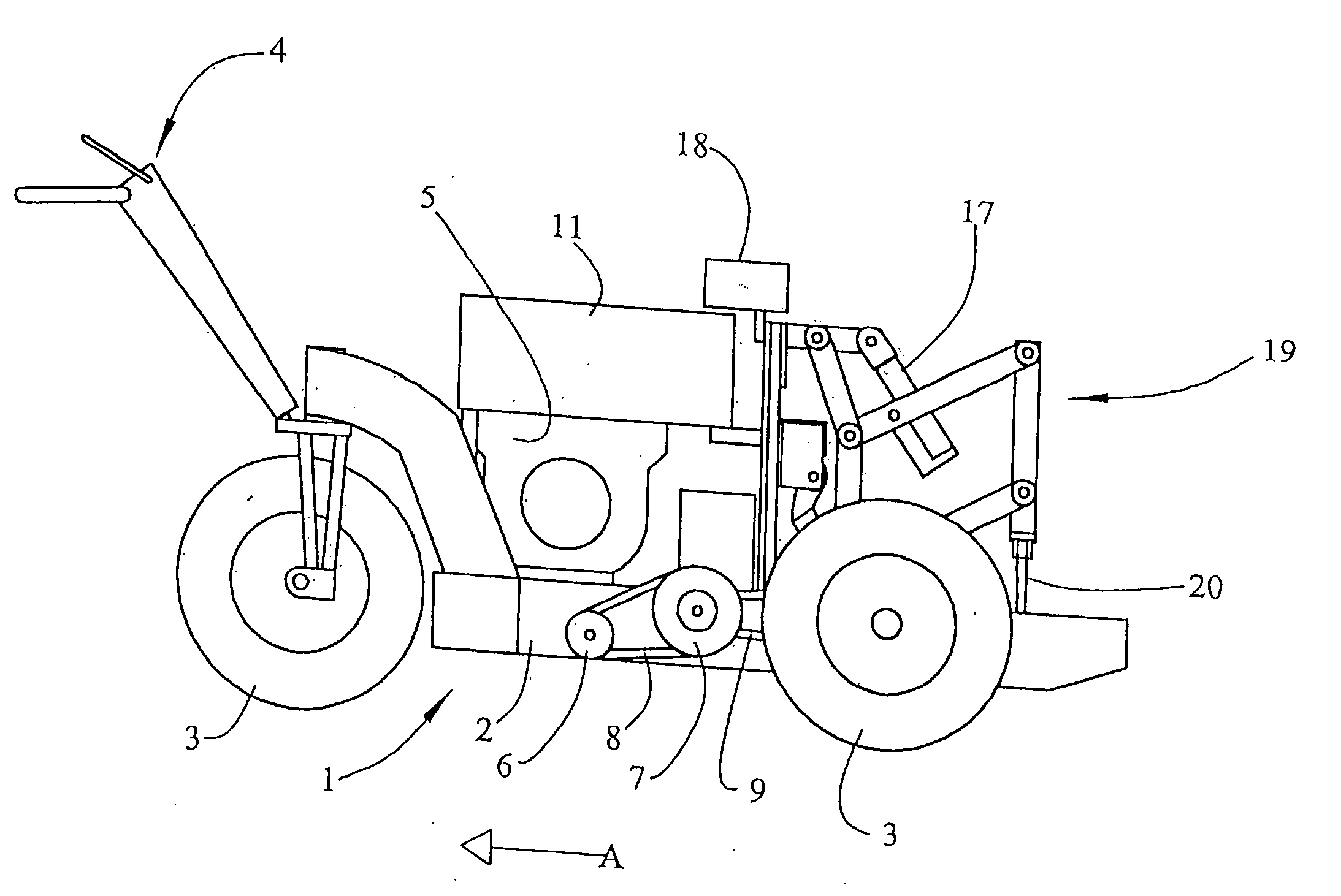
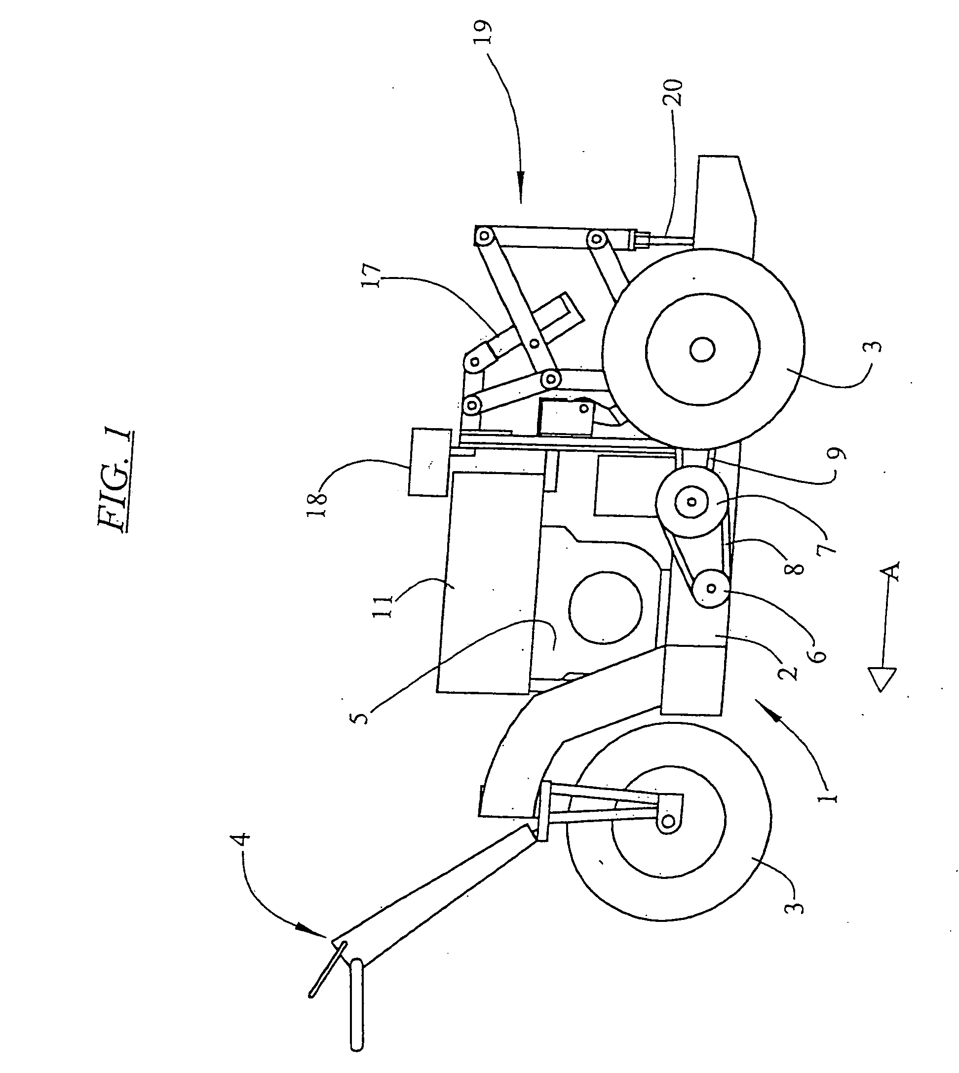
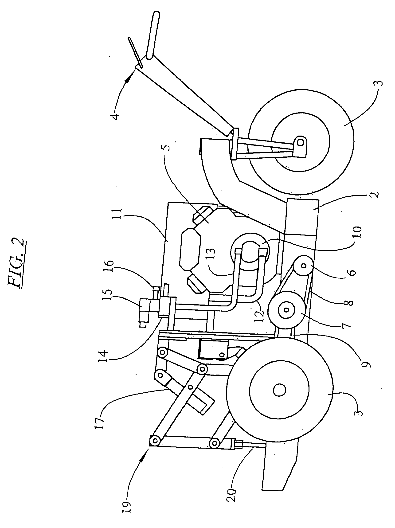
[0013] The link arm arrangement of the cultivator device allows the follower and the tool support member to linearly move in the second direction during engagement with the ground surface as the support frame moves over the ground surface. That is, the first and second pairs of link arms compensate for the increasing distance between the support frame and the tool support member caused by the support frame moving along the ground surface so that the tool support member is effectively stationary when the cultivation tool is engaged in the ground surface.
[0014] Preferably, the first direction is substantially parallel to the ground surface while the second direction is preferably substantially perpendicular to the ground surface. In this form of the invention, the tool support member is kept substantially perpendicular relative to the ground surface when penetrating and withdrawing from the ground surface. This in turn ensures that a substantially perpendicular hole is produced, avoiding any ragged edges and undesirable pressure on the side wall of the tined hole.
[0015] In addition, the cycle time can be varied quite easily by increasing the frequency in which the driver operates (hereinafter referred to as the “driver frequency”), thereby producing more holes in a given surface area. There is no tendency for the tine to propel the cultivator so that if the cultivator device is scaled up in size, the driver frequency can be increased to ensure that the same number of holes for a given surface area is produced, compensating for the larger distance between “hits”. This avoids the difficulty in scaling up of the known cultivator where the flywheel radius imposes a physical constraint.
[0020] In one embodiment the driver is a linearly operable device such as hydraulic or pneumatic cylinder controlled by a hydraulic or pneumatic circuit. In another embodiment the driver is a mechanical arrangement which imparts reciprocating movement to the link arm assembly. Preferably, the mechanical arrangement includes a flywheel and a connecting rod. The connecting rod is preferably connected to one of the first pair of link arms. The flywheel is preferably driven in rotation by a suitable power source, for example by vee belt connection. The connection between the drive and link arm assembly, for example the hydraulic cylinder or connecting rod is preferably arranged to aid the desired overall movement in the first direction during each part of the cycle of operation. That is the driver connection preferably aids movement of the tool support away from the support frame during at least part of the cycle time in which the ground is engaged. More preferably, the movement is aided at the critical time on the upstroke as the tool is emerging from the ground. Preferably the driver connection also aids movement of the tool support toward the support frame at the end of the cycle following completion of ground engagement.
[0022] In one embodiment a stop is located on the follower for dampening forces produced by the driver in returning the follower to the rest position. The stop is preferably located at one corner of the parallelogram. The corner is preferably the corner that is closest to both the support frame and the ground surface.

Problems solved by technology

In conducting this type of aeration of turf surfaces, the neatness of the edges of the hole made by the cultivator can significantly affect the overall result.
For example in the case of golfing or bowling greens and the like where the vegetation is short, a hole with rough edges or too large a hole can cause spot erosion, resulting in an undesirable dimple in the ground surface.
Often this problem is encountered in cultivators powered by a link to a prime mover (such as a tractor), where difficulties in synchronising the speed of the hole making tool with the speed of the prime mover, arises, for example due to different gear ratios between the driving wheels of the tractor and the power link.
While this cultivator achieves fairly neat holes in ground surfaces such as turf, the free pivoting arrangement of the cultivation tool restricts the depth of holes that can be produced.
This is at least partly the result of the above described cultivator not being suitable for scaling up in size.
While it has been proposed to use a plate of increased area to cover this increased distance (using a larger number of tines per plate), such plates are unwieldy and awkward as well as requiring greatly increased power to effect penetration of the larger number of tines.

Method used


Image

  • Cultivating device
  • Cultivating device
  • Cultivating device

Examples


second embodiment

[0072]FIG. 14 shows the present invention using a mechanical driver. The link arm assembly 19 of this embodiment is identical to that described in relation to FIGS. 1 to 13 and the description will not be repeated. The same reference numerals have been used to identify corresponding features.

[0073] The cultivator 60 of the second embodiment is designed for attachment to the three point linkage of a tractor (not shown). Support frame 2 is modified to include upper and lower three point linkage attachments 61, 62 of conventional type. The cultivator 60 is driven via an input shaft 63 that is coupled with the power take off of a tractor (not shown). Input shaft 63 drives a gearbox 64 which in turn drives a pulley 65. Pulley 65 drives a jack shaft pulley 66 via conventional V-belt 67. The jack shaft pulley 66 in turn drives a flywheel 68 using a conventional V-belt 69. The flywheel 68 is thus driven in rotation by the power take off of the tractor in a conventional manner. A connecting ...

third embodiment

[0074]FIGS. 15 and 16 illustrate a third embodiment cultivating device 100 having a revised dampening arrangement within a housing 130. In all other respects the cultivating device is the same as that shown and described in FIG. 14. Although the cultivating device 100 is illustrated as a mechanically driven cultivating device, the dampening arrangement can also be applied to other cultivating devices, such as the cultivating device shown and described in FIGS. 1 through 13.

[0075]FIGS. 15 and 16 illustrate the cultivating device in the same position as shown in FIGS. 6 and 14. The position illustrated is at top of stroke for the tool support 34 and tine 20. According to the dampening arrangement, the dampener 43, heretofore described in FIGS. 6 and 14, is replaced with a dampening block 143. The bias element 41 is replaced with a smaller vertical profile bias element 141 supported on a fixed block 142. The profile of the arm 25 on which the pedal 42 is mounted provides a cam surface ...


PUM


Abstract

A cultivator for aerating a ground surface. The cultivator has a support frame moveable relative to the ground surface and a follower first pivotally connected to the support frame by a first pair of spaced link arms. The link arms have two pairs of equidistantly spaced pivot points for linear movement of the follower in a first direction away from the support frame. A tool support member is pivotally connected to the follower by a second pair of spaced link arms. The second link arms have two pairs of equidistantly spaced pivot points for linear movement of a cultivating tool in a second direction substantially perpendicular to the first direction. A driver effects cyclic movement of the tool support member in the second direction and movement of the follower in the first direction. A bias element provides resilient damping of the movement of the follower along the first direction away from the support frame, wherein the resilient damping is provided at an extremity of movement of the follower outward from the support frame along the first direction, to urge the follower in the direction of inward movement toward the support frame. A dampening element provides resilient damping of the movement of the follower along the first direction toward the support frame, the resilient damping provided at an extremity of movement of the follower inward toward the support frame in the first direction to progressively arrest movement of the follower in the direction of inward movement toward the support frame.

Description

FIELD OF THE INVENTION [0001] This invention relates to a cultivator for aerating ground surfaces. The invention has particular application to cultivators for aerating turf surfaces, such as golf courses, sporting grounds, bowling greens and the like. BACKGROUND ART [0002] Cultivators of this type are used for maintaining landscaped ground surfaces, including turf. In this sense the term “turf” refers to grass and other material which is specifically grown for playing sport and used for example to form golf course greens, sporting fields and bowling greens. Cultivators are frequently used on these types or surfaces for repeatedly penetrating the ground surface, forming a plurality of holes so that the ground surface is aerated, to improve growth of the grass or other material and enhance the condition of the surface for playing purposes. [0003] In conducting this type of aeration of turf surfaces, the neatness of the edges of the hole made by the cultivator can significantly affect ...

Claims


Application Information

Patent Timeline
Patent Type & Authority Applications(United States)
IPC IPC(8): A01B45/02
CPCA01B45/023
Inventor BANKS, JOHN
Owner DEERE & CO
Learn More