Reinforcing steel support

Inactive Publication Date: 2005-12-01
WILSON GUY
View PDF8 Cites 2 Cited by
  • Summary
  • Abstract
  • Description
  • Claims
  • Application Information

AI Technical Summary

Benefits of technology

[0007] In accordance with the present invention, a support for suspending concrete reinforcing steel ho

Problems solved by technology

One area of concrete construction that is found most labor intensive involves the pouring of grade beams because it is difficult and time consuming to position the reinforcing steel or re-bar properly.
Many times a worker becomes frustrated with the task and haphazardly positions the re-bar to accomplish the task more quickly.
The use of wooden beams is a very laborious and time consuming process requiring the positioning of a considerable number of beams to support many lengths of reinforcing steel at different elevations.
Furthermore, once the reinforcing structure has been constructed it must be lowered onto footings, which requires the removal of the supporting wooden beams.

Method used


Image

  • Reinforcing steel support
  • Reinforcing steel support
  • Reinforcing steel support

Examples


Embodiment Construction

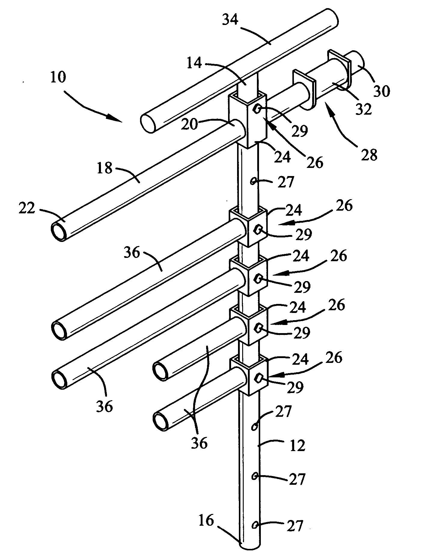
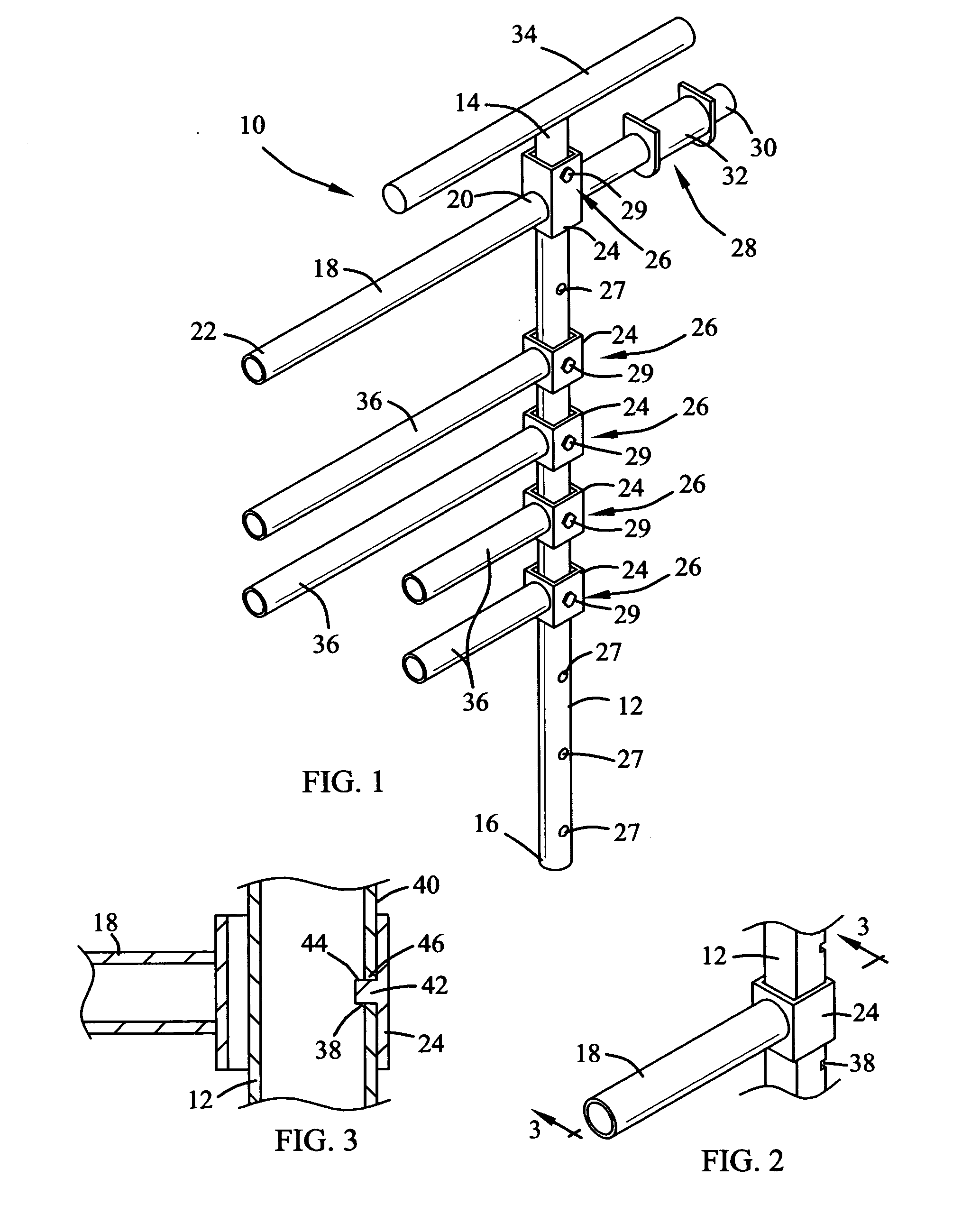
[0020] Referring now to the drawings, and particularly to FIGS. 1-2, a preferred embodiment of the support for reinforcing steel of the present invention is shown and generally designated by the reference numeral 10.

[0021] Referring to FIG. 1, the support 10 includes a vertical member 12 having a first end 14 and a second 16. Preferably, the vertical member 12 is of a tubular section of a circular cross-section. A support arm 18 extends from and orthogonal to the vertical member 12 at a selected position or elevation between the first and second ends 14 and 16. Preferably, the support arm 18 is of a cantilever type and is only supported by the vertical member 12 at one end 20 with the opposite end 22 projecting in a direction away from the vertical member. Most preferably, the support arm 18 is of a tubular section. The end 20 of the support arm 18 can define a channel section 24 which is adapted to slidably receive the vertical member 12 so that the support arm can be selective po...


PUM


Abstract

A support for suspending reinforcing steel relative to a form wall at a spaced distance is provided. The support includes a vertical member having a first end and a second end, a cantilever support arm extending from the vertical member for supporting a length of reinforcing steel orientated horizontally at a predetermined elevation and at a spaced distance from the form wall, and a clamp means for securing the support to the form wall so that the support arm is perpendicular to the form wall and extends towards the opposite side of the form. A plurality of support arms can be provided for suspending many different lengths of reinforcing steel at different elevations. The support is intended to be used in the construction of reinforcing structures, as for grade beams and is removed from the form wall prior to the pouring of concrete into the form.

Description

BACKGROUND OF THE INVENTION [0001] 1. Field of the Invention [0002] The present invention relates generally to a device for positioning concrete reinforcing steel, such as re-bar. More particularly, relating to an apparatus for suspending concrete reinforcing steel relative to a form wall during the construction of a concrete reinforcing structure of reinforcing steel. [0003] 2. Background of the Invention [0004] In concrete construction it is customary to use concrete reinforcing steel or re-bar to strength a poured concrete structure. To provide the highest level of reinforcement with installation of re-bar in concrete, the re-bar must be accurately and strategically oriented for maximum benefit. One area of concrete construction that is found most labor intensive involves the pouring of grade beams because it is difficult and time consuming to position the reinforcing steel or re-bar properly. Many times a worker becomes frustrated with the task and haphazardly positions the re-b...

Claims


Application Information

Patent Timeline
IPC IPC(8): E04B2/00E04C5/16E04G21/18
CPCE04G21/185E04C5/168
Inventor WILSON, GUY
Owner WILSON GUY
Why Eureka
Try Eureka