Transducer identification

a technology of transducer and identification plate, which is applied in the direction of measurement device, transmission monitoring, instruments, etc., can solve the problems of difficult to determine compatibility information, and achieve the effect of optimizing the overall performance of the system and optimizing the performan

Active Publication Date: 2005-11-24
AIRMAR TECH
View PDF42 Cites 6 Cited by
  • Summary
  • Abstract
  • Description
  • Claims
  • Application Information

AI Technical Summary

Benefits of technology

[0007] The present invention provides additional information to the fishfinder device or echosounder. The additional information allows the echosounder to alter its functionality or parameters to optimize performance. Examples of types of information provided by the present invention include, but are not limited to, a) the resonant frequency of the transducer; b) the impedance of the transducer at the transducer's resonant frequency; c) the transducer's power rating; d) the date of manufacture of the transducer; e) the peak transmitting voltage response of the transducer; f) the receiving voltage response of the transducer; g) the figure of merit of the transducer; h) the model number of the transducer; i) the serial number of the transducer; j) the transducer's aging coefficient (i.e. the rate at which the transducer's resonant frequency changes over time); k) information regarding the configuration of the transducer, such as the housing style, arrangement of piezoelectri

Problems solved by technology

Often, the transducer is installed in a difficult-to-access location, and identification markings may have bec

Method used


Image

  • Transducer identification
  • Transducer identification
  • Transducer identification

Examples


Embodiment Construction

[0019] A description of preferred embodiments of the invention follows.

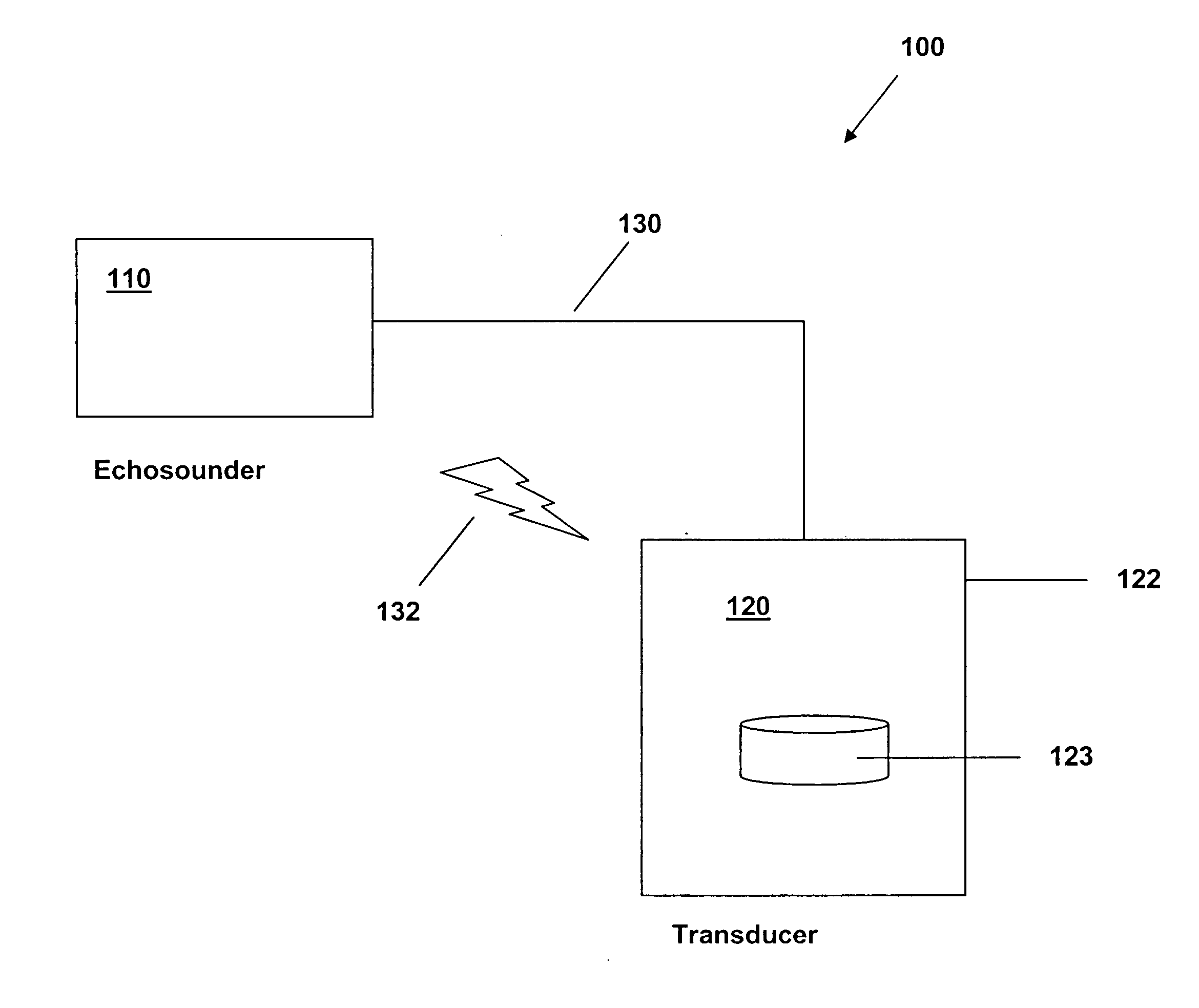
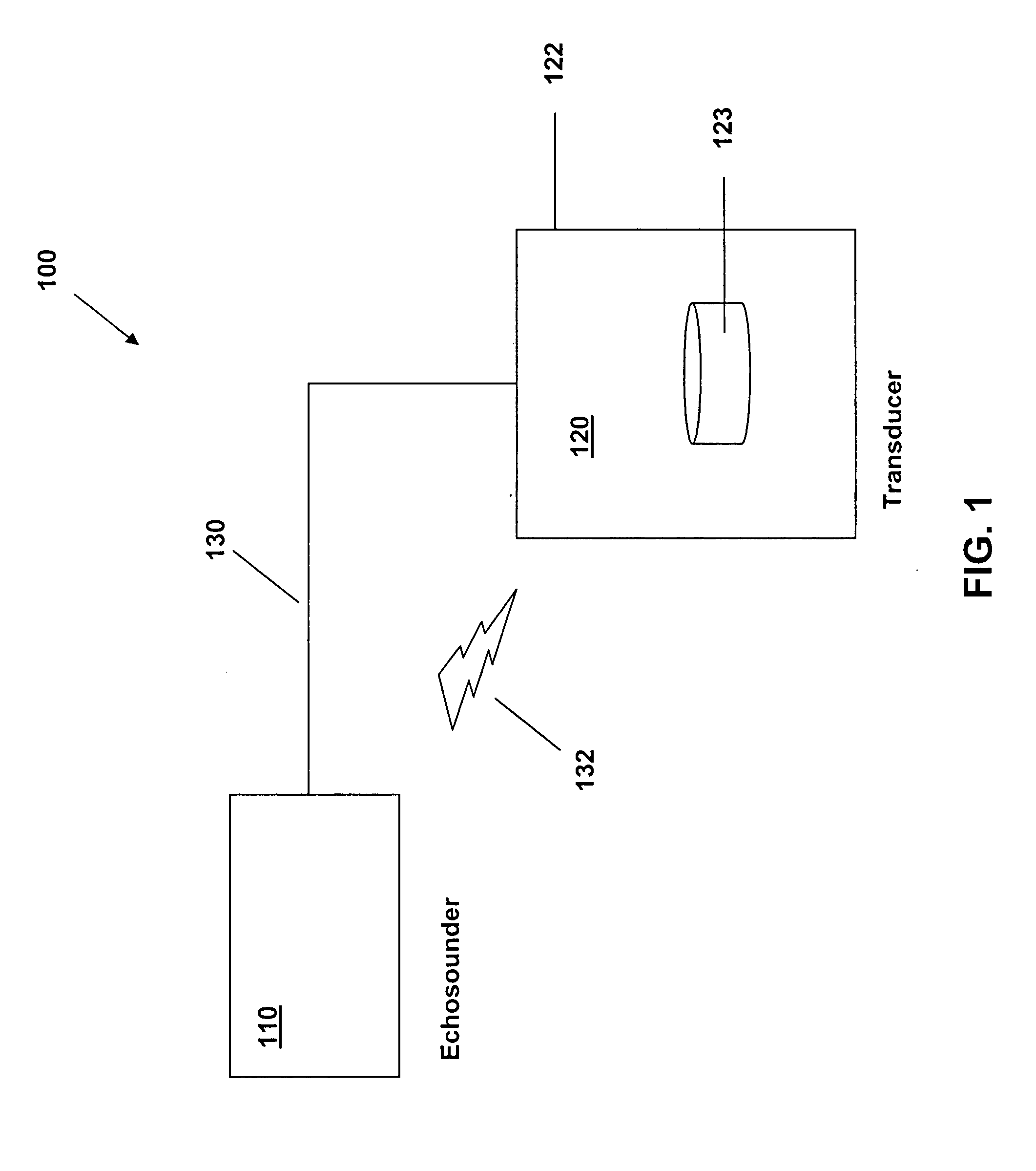
[0020] In general, an echosounder and its associated ultrasonic transducer are located in two separate areas of a marine vessel. The echosounder and associated circuitry is typically located in the vessel's driving station and includes a display for providing information to the operator. On the other hand, the ultrasonic transducer per se is typically mounted on the vessel below the waterline for generating an ultrasonic pulse and receiving echoes from objects in the water, or the bottom surface. The echosounder does not know what type of transducer it will be connected to and its specific characteristics. These characteristics, if known by the echosounder can be used to optimize the performance of the overall system and / or to protect the ultrasonic transducer from overdrive. Optimization can be as simple as altering a feature set or parameters of the echosounder. Types of characteristics include, but are not li...


PUM


Abstract

A transducer identification system provides transducer characteristic information to an echosounder. The echosounder, in turn, utilizes the transducer characteristic information to alter its functionality or parameters to optimize its performance. The transducer characteristic information can be any combination of a) the resonant frequencies of the transducer; b) the impedances of the transducer at the transducer's resonant frequencies; c) the transducer's power rating; d) the date of manufacture of the transducer; e) the peak transmitting voltage response of the transducer; f) the receiving voltage response of the transducer; g) the figure of merit of the transducer; h) the model number of the transducer; i) the serial number of the transducer; j) the transducer's aging coefficient; k) information regarding the configuration of the transducer, such as the housing style, arrangement of piezoelectric elements, and type of acoustic window; l) the beam width of the transducer; m) configuration and calibration information regarding an included temperature sensor; and n) configuration and calibration information regarding an included speed sensor.

Description

RELATED APPLICATION [0001] This application claims the benefit of U.S. Provisional Application No. 60 / 569,785, filed on May 10, 2004, the entire teachings of which are herein incorporated by reference.BACKGROUND OF THE INVENTION [0002] Sonar devices are well known in the art and find widespread use in sport fishing, navigation, scuba diving, as well as any number of other recreational or commercial activities. Typically, a sonar system will include a sonar unit, which includes a display for providing information to the operator, and a transducer which is mounted under the waterline for generating an ultrasonic pulse and receiving echoes from objects in the water, or the bottom surface. The electronic circuitry for driving the transducer to transmit an acoustic pulse and for amplifying and filtering received echoes has traditionally been located in the sonar unit. Locating such circuitry in the sonar unit has, heretofore, provided a number of advantages, such as: there is more likely...

Claims


Application Information

Patent Timeline
IPC IPC(8): G01S7/00G01S7/52G01S7/524G01S15/00G01S15/96
CPCG01S7/003G01S15/96G01S7/524G01S7/52
Inventor SIFFERMAN, ANDREW M.BOERICKE, FREDERIC S. IIBOUCHER, STEPHEN G.
Owner AIRMAR TECH
Why Eureka
Try Eureka