Eureka AIR delivers breakthrough ideas for toughest innovation challenges, trusted by R&D personnel around the world.

Handle assembly for tool

a technology for tools and handles, applied in the field of handle assemblies for tools, can solve the problems of limiting the length of time during which the tool can be used continuously, difficult for a user of the tool to maintain a grip, and significant vibration, and achieve the effect of simplifying the assembly of the tool and reducing the cost of tool manufactur

Inactive Publication Date: 2005-11-24
BLACK & DECKER INC
View PDF36 Cites 32 Cited by
  • Summary
  • Abstract
  • Description
  • Claims
  • Application Information

AI Technical Summary

Benefits of technology

[0011] By providing at least one flexible member and at least one chamber containing at least one vibration damping gel material between the engaging portion and the surface of the handle in use, this provides the advantage of enabling the material of the flexible member to be chosen to have the optimum frictional properties to enable a user to maintain a grip on the tool, and the vibration damping gel material at the same time to have the optimum vibration damping properties. In particular, it is possible to provide gel materials having a wide range of vibration damping properties compared with air. This also provides the advantage of simplifying construction of the assembly, which in turn reduces the cost of manufacture of the assembly, as well as providing the advantage of further reducing the cost of manufacture of the assembly by providing one or more components which perform more than one function.
[0013] This provides the advantage of enabling the blister pack to conform to the shape of the tool handle.
[0015] This provides the advantage of facilitating folding of the blister pack.
[0020] This provides the advantage of enabling visible indicia, such as decorative features or trade marks, or electrical indicators, for example indicating that the tool of which the assembly forms part is actuated, to be seen while the tool is in use.
[0023] This provides the advantage of enabling said indicium to provide an indication of an operating condition of a power tool, such as whether the tool is actuated.
[0026] This provides the advantage of simplifying assembly of the tool, which in turn further reduces the cost of manufacture of the tool.

Problems solved by technology

Known power tools, such as power drills in which a drill bit is rotated by an output shaft which is in turn rotated by means of an electric motor, generate significant amounts of vibration, which can under certain circumstances limit the length of time during which the tool can be used continuously.
In addition, the housing of such tools is generally made from a durable plastics material on which it can be difficult for a user of the tool to maintain a grip when the tool is in use for a sustained period.
This known arrangement suffers from the drawback that because the softer material performs the dual functions of providing a friction grip and vibration damping, the choice of material constitutes a compromise in that although it will have acceptable friction reducing and vibration damping properties, the performance of the handle is limited because a material having optimum frictional properties will generally have unacceptable vibration damping properties, and vice versa.
This known arrangement suffers from the drawback that the vibration damping properties of air can only be varied by adjusting the air pressure within a chamber containing the air, and even then, the range of vibration damping properties achievable is limited.
Furthermore, it is difficult, and therefore expensive, to manufacture a sealed chamber containing air having a predetermined pressure.

Method used


Image

  • Handle assembly for tool
  • Handle assembly for tool
  • Handle assembly for tool

Examples


Embodiment Construction

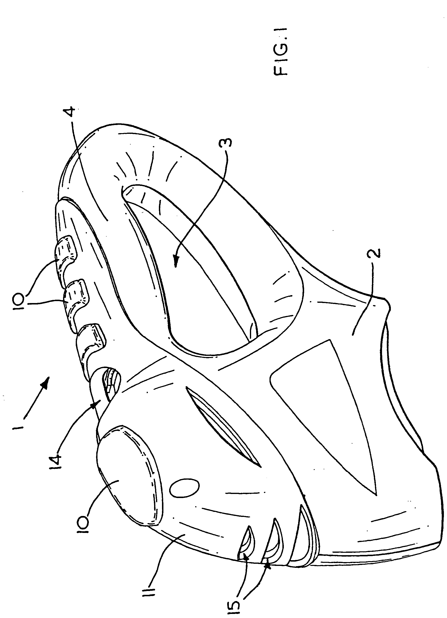
[0040] Referring to FIGS. 1 and 2, a power tool 1 such as a drill or jigsaw comprises a housing 2 defining an aperture 3 bounded on one side thereof by a handle 4, the housing 2 containing a motor (not shown) for actuating an output member such as a drill bit or jigsaw blade (not shown).

[0041] The housing 2 is formed from a generally durable plastics material, as will be familiar to persons skilled in the art, and has a recessed portion 5 on a generally smooth upper surface of the handle 4, the recessed portion 5 being provided with a recess 6 containing an actuating switch (not shown) for turning the tool 1 on and off. The housing 2 is provided with ventilation apertures 7 at one end of the recessed portion 5 to allow cooling of the interior of the housing 2.

[0042] A flexible sheet 8, of thermoplastic elastomeric material, such as a thin layer of polyurethane, having a coefficient of friction higher than that of the material from which the housing 2 is made, is formed by means of...


PUM


Abstract

A handle assembly for a power tool 1 comprises a housing 2 defining a handle 4 and housing a motor for actuating an output member of the tool, such as a drill bit or jigsaw blade. The handle assembly comprises at least one flexible sheet 8 adapted to be mounted to a surface of the handle of the power tool and having a series of protrusions 10 adapted to be engaged by a hand of a user of the tool. The protrusions 10 retain one or more blister packs (not shown) containing at least one vibration damping gel material between the flexible sheet 8 and the surface of the handle 4.

Description

FIELD OF THE INVENTION [0001] The present invention relates to handle assemblies for tools, and relates particularly, but not exclusively, to handle assemblies having combined friction gripping and vibration damping properties, for power tools in which an output shaft is driven by a motor. BACKGROUND OF THE INVENTION [0002] Known power tools, such as power drills in which a drill bit is rotated by an output shaft which is in turn rotated by means of an electric motor, generate significant amounts of vibration, which can under certain circumstances limit the length of time during which the tool can be used continuously. In addition, the housing of such tools is generally made from a durable plastics material on which it can be difficult for a user of the tool to maintain a grip when the tool is in use for a sustained period. [0003] U.S. Pat. No. 6,308,378 discloses a gripping arrangement for a handle of a power tool in which the sides of the handle are provided with frictional grippi...

Claims


Application Information

Patent Timeline
IPC IPC(8): B25F5/00
CPCB25F5/006
Inventor COOPER, VINCENT P.
Owner BLACK & DECKER INC
Why Eureka
Eureka Blog
Learn More