
Output shaft assembly for power tool and power tool incorporating such assembly

a technology of output shaft and assembly, which is applied in the direction of power driven reciprocating saws, manufacturing tools, metal sawing devices, etc., can solve the problems of large width of forward part of jigsaw around the output shaft, and it is not possible to provide a scroller mode of such jigsaws, so as to reduce the cost of manufacturing a tool and simplify the construction of the output shaft

Inactive Publication Date: 2005-11-24
BLACK & DECKER INC
View PDF51 Cites 10 Cited by
  • Summary
  • Abstract
  • Description
  • Claims
  • Application Information

AI Technical Summary

Benefits of technology

[0008] By providing an output shaft having first and second portions adjacent respective ends of the shaft and having non-circular cross-section in a direction transverse to a longitudinal axis of the shaft, and at least one third portion between the first and second portions and having at least partially substantially circular external cross-section section in a direction transverse to the longitudinal axis of the shaft to allow the shaft to pivot about the longitudinal axis relative to a drive mechanism for driving the shaft in a reciprocating motion relative to the tool housing, this provides the advantage of combining the benefits of a substantially flat output shaft enabling a more compact construction of the tool in the vicinity of the output shaft, and rotation of the output shaft relative to a drive mechanism, for example to provide a scroller mode when the tool is a jigsaw.
[0010] This provides the advantage of simplifying construction of the output shaft, which in turn reduces the cost of manufacture of a tool incorporating the output shaft.

Problems solved by technology

This causes the disadvantage that the slots with which the cross pins cooperate must be as long as the distance of travel of the cross pins in an axial direction in order to ensure permanent engagement of the cross pins with the slot, as a result of which the overall height of the jigsaw is large, which obstructs viewing of the jigsaw blade during cutting thereof, and the width of the forward part of the jigsaw around the output shaft is also large as a result of this.
However, it has not been possible to provide a scroller mode of such jigsaws because of the difficulty in making the output shaft rotatable relative to the jigsaw housing.

Method used


Image

  • Output shaft assembly for power tool and power tool incorporating such assembly
  • Output shaft assembly for power tool and power tool incorporating such assembly
  • Output shaft assembly for power tool and power tool incorporating such assembly

Examples


Embodiment Construction

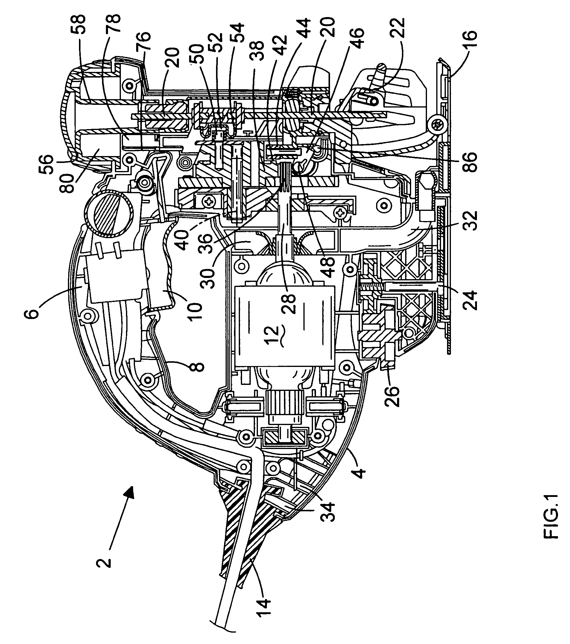
[0039] Referring to FIG. 1, a jigsaw 2 has a housing 4 comprising two clam shell halves 6 (only one of which is shown in FIG. 1) defining a handle 8 having a trigger switch 10 for operating a motor 12 supplied with electrical power via a cable 14. A shoe 16 for resting on a workpiece (not shown) is located at a lower part of the housing 4, and a jigsaw blade 18 (FIG. 2) is attached to the lower end of an output shaft 20 by means of a blade clamp mechanism 22. The operation of the blade clamp mechanism 22 is not relevant to an understanding of the present invention and will therefore not be described in greater detail herein. The orientation of the shoe 16 is adjustable relative to the housing 4 to enable bevel cutting, and can be fixed by means of a clamping screw 24 operated by a locking mechanism 26, which is also not relevant to an understanding of the present invention and will therefore not be described in greater detail.

[0040] The motor 12 drives a shaft 28 which carries a fa...


PUM


Abstract

An output shaft assembly for a jigsaw having a tool housing, a motor arranged in the tool housing, and an output shaft adapted to be driven in a reciprocating motion relative to the tool housing by means of the motor and to support jigsaw blade for reciprocating motion of the blade relative to the tool housing is disclosed. The output shaft assembly comprises an output shaft (20) of generally flat cross section and having a pair of generally D-shaped inserts (94) to form a region of generally circular external cross-section to allow the output shaft (20) to pivot relative to a scotch yoke mechanism (54) for driving the output shaft in a reciprocating motion relative to the tool housing. A jigsaw incorporating the output shaft assembly is also disclosed.

Description

FIELD OF THE INVENTION [0001] The present invention relates to an output shaft assembly for a power tool, and relates particularly, but not exclusively, to an output shaft assembly for a jigsaw having a scrolling mode (i.e. in which an output shaft supporting a jigsaw blade can rotate about its longitudinal axis relative to the jigsaw housing) and an orbital mode (i.e. in which the output shaft is pivotable relative to the housing about an axis transverse to its longitudinal axis, so that an oscillating motion is superimposed on the axial reciprocating motion of the jigsaw blade). The invention also relates to a power tool incorporating such an output shaft assembly. BACKGROUND OF THE INVENTION [0002] A jigsaw having scrolling and orbital modes is disclosed in EP 0158325. The jigsaw has an output shaft of generally circular cross section in order to enable the output shaft to pivot about its longitudinal axis in the scrolling mode of the jigsaw relative to a scotch yoke mechanism dr...

Claims


Application Information

Patent Timeline
IPC IPC(8): B21J1/00B23D49/00B23D49/16B23D51/10B23D51/16B23Q1/00B27B19/09
CPCB23D49/167
Inventor MILLION, PHIL
Owner BLACK & DECKER INC
Learn More