
Apparatus and method for high rate uniform coating, including non-line of sight

a technology of uniform coating and apparatus, applied in the direction of solid-state diffusion coating, plasma technique, vacuum evaporation coating, etc., can solve the problems of high equipment cost of eb-pvd, metal and ceramic coatings can be quite costly to apply, and the effect of reducing the cost of eb-pvd

Active Publication Date: 2005-11-17
UNIV OF VIRGINIA ALUMNI PATENTS FOUND
View PDF3 Cites 41 Cited by
  • Summary
  • Abstract
  • Description
  • Claims
  • Application Information

AI Technical Summary

Benefits of technology

[0013] The present invention comprises a method for applying at least one coating on at least one substrate on at least a non-line of sight region of the substrate comprising the steps of: presenting at least one of the substrates to a chamber; wherein the chamber's down stream pressure, Pc, has an operating range from about 10−4 to about 10−3 Torr; presenting at least one evaporant source to the chamber; presenting carrier gas streams comprised of gas molecules to the chamber, wherein the carrier gas streams being defined by a pressure ratio that gives the carrier gas molecules a given flow velocity, νf, impinging at least one the evaporant sources with at least one electron energetic beam in the chamber to generate an evaporated vapor flux comprised of evaporant molecules; and deflecting at l

Problems solved by technology

Electron beam—physical vapor deposition (EB-PVD) of metal and ceramic coatings can be quite costly to apply due to high equipment cost, low deposition efficiencies and relatively low deposition rates.
The high equipment costs of EB-PVD are a result of the high vacuum environment, which is necessary during deposition (typically below 10−6 Torr), the high cost of high power electron beam guns and the sophisticated component manipulation systems needed to achieve uniform and conformal (non line-of-sight) coating on non-planar substrates.
The operating pressure defines the vacuum pump requirements with lower pressures generally needing more expensive pumps.
However, despite the many needs, the advancement of processing approaches for these applications above are limited by several factors.
Namely, the inability to uniformly coat such substrates without sophisticated substrate translation and rotation capabilities the inability to deposit metal, alloys and ceramics with the same process and low deposition rates which often limit high volume throughputs.
However, the deposition rates can be low and the process often requires the use of toxic (and expensive) precursor materials [18].
The deposition of multicomponent alloys can also be challenging.
Although useful for depositing elemental layers, this process is less suitable for the creation of alloy or ceramic coatings [18].
The high vacuums employed in these techniques result in few collisions with the background gas resulting in “line-of-sight” coating.
However, the materials utilization efficiency (MUE) of electron beam physical vapor deposition is often low (especially for the case of very small substrates such as fibers or wires).
When a relatively long source to substrate distances is required, the deposition efficiency can be low and the deposition rate limited.

Method used


Image

  • Apparatus and method for high rate uniform coating, including non-line of sight
  • Apparatus and method for high rate uniform coating, including non-line of sight
  • Apparatus and method for high rate uniform coating, including non-line of sight

Examples


example 1

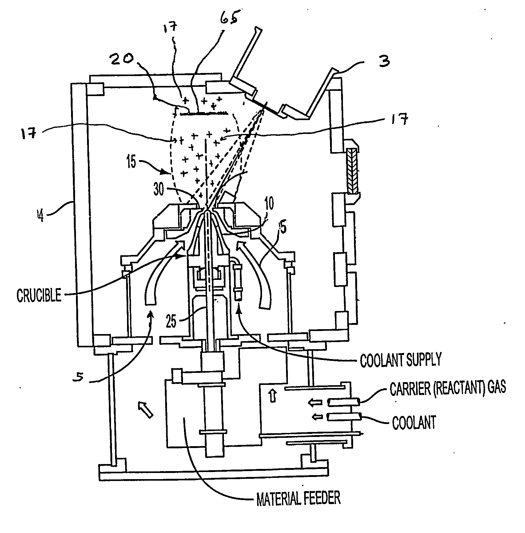
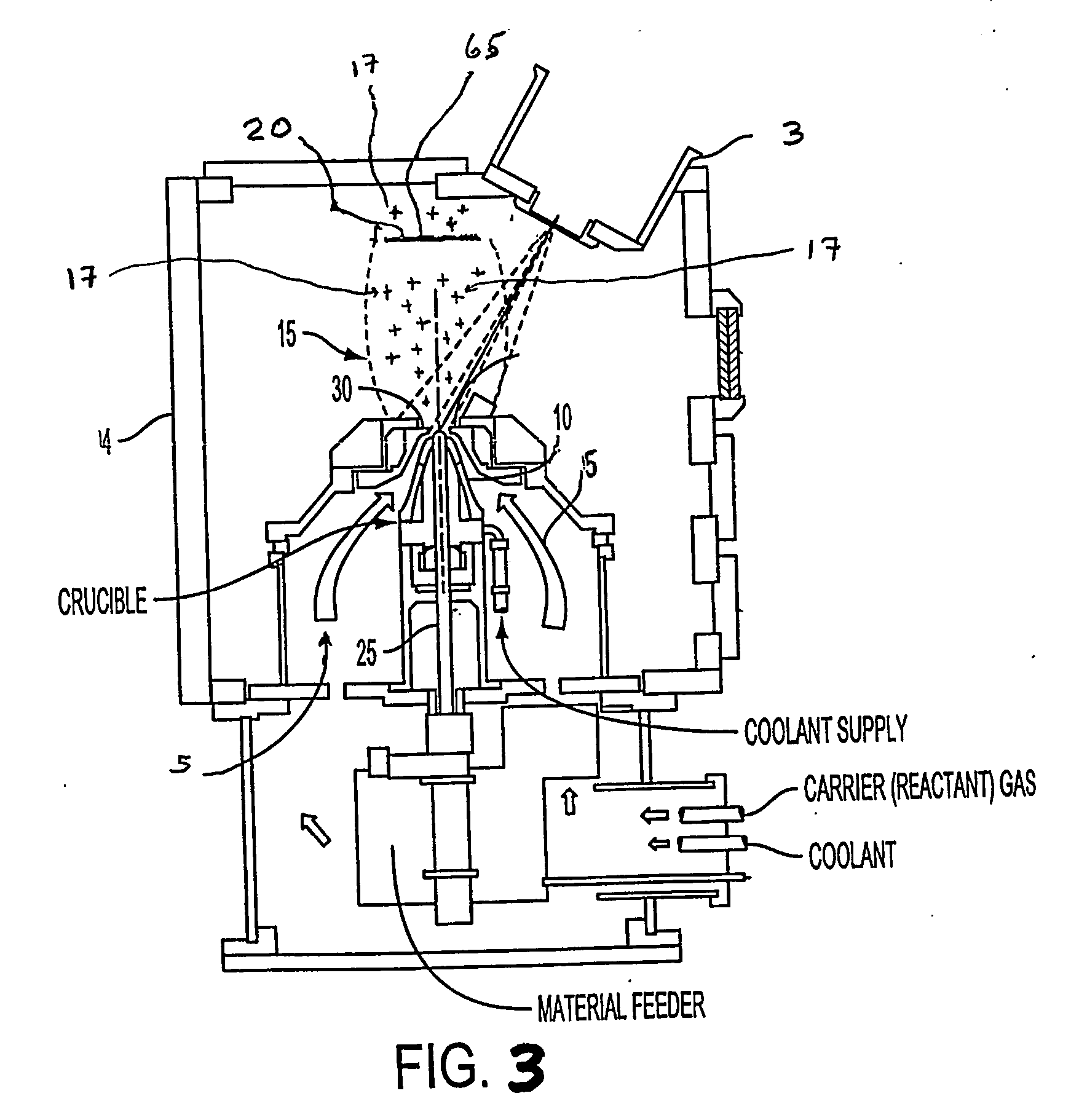
[0059] Still referring to FIG. 3, aluminum coatings were produced using a DVD approach with the DVD apparatus 1 having a chamber 4. Aluminum vapor 15 was created by electron beam evaporation from a 0.127 cm diameter aluminum source rod (purity four 9's) 25 (or other material as desired) and deposited on a 380 μm diameter stainless steel fiber 65 as the substrate 20. A 13 cm long wire / fiber was positioned 15.0 cm from the nozzle 30. The midsection of the fiber was located directly above the center of the vapor source 25. The chamber pressure was 16 Pa. Coatings were produced with a pressure ratio of 7.0, 4.5 and 2.0. The aluminum was evaporated at a rate of 67, 58 and 53 mg / min. for three pressure ratios respectively. Evaporation was allowed to continue until the desired thickness (20 to 100 μm) was achieved. The deposition rate varied from 2 to 30 μm / min. on the front side 22 (line of sight side or region) of the fibers (i.e. the side faced the evaporation source) and 0.2 and 2 μm / m...

example no.2

EXAMPLE NO. 2

[0079]FIG. 15 depicts an exemplary embodiment of the present invention apparatus in operation. In the exemplified DVD apparatus 1, material 25 is vaporized using an energetic beam 3. The vapor flux 15 is focused by a carrier gas 5 and directed into a substrate 20 (i.e., object, target or region thereof), such as wire or fiber 65. A feeder spool 127 or the like advances the wire or fiber 65 (such as an array, mesh, or mat) so as to receive a first pass 124 and a second pass 129 of coating(s) before being taken up by the take up spool 128 or the like.

[0080] Turning to FIGS. 17(A)-(B), FIG. 17(A) schematically illustrates a desired LOS coating 22 and NOLS coating 21 deposited on the fiber wire 65 on a first pass. Additionally, FIG. 17(B) schematically illustrates a desired LOS coating 122 and NOLS coating 121 deposited on the fiber wire 65 on a second pass.

example no.3

EXAMPLE NO. 3

[0081]FIG. 20 depicts an exemplary embodiment of the present invention apparatus in operation. In the exemplified DVD apparatus 1, material 25 is vaporized using an energetic beam 3. The vapor flux 15 is focused by a carrier gas 5 and directed into a substrate 20 (i.e., object, target or region thereof), wherein the substrate 20 is at least substantially parallel with the general flow of the carrier gas 5. It should be appreciated that the angle or alignment can be adjusted as desired.

[0082] In conclusion, the present invention provides an improved method and apparatus for applying a coating to a substrate using an energetic beam—directed vapor deposition (EB-DVD) having numerous advantages as discussed supra and infra, but not limited thereto. The present invention method and apparatus improves material utilization efficiency of the deposition process.

[0083] Second, the present invention method and apparatus increases the deposition rate applied to LOS and NLOS regio...


PUM

PropertyMeasurementUnit
Lengthaaaaaaaaaa
Pressureaaaaaaaaaa
Lengthaaaaaaaaaa

Abstract

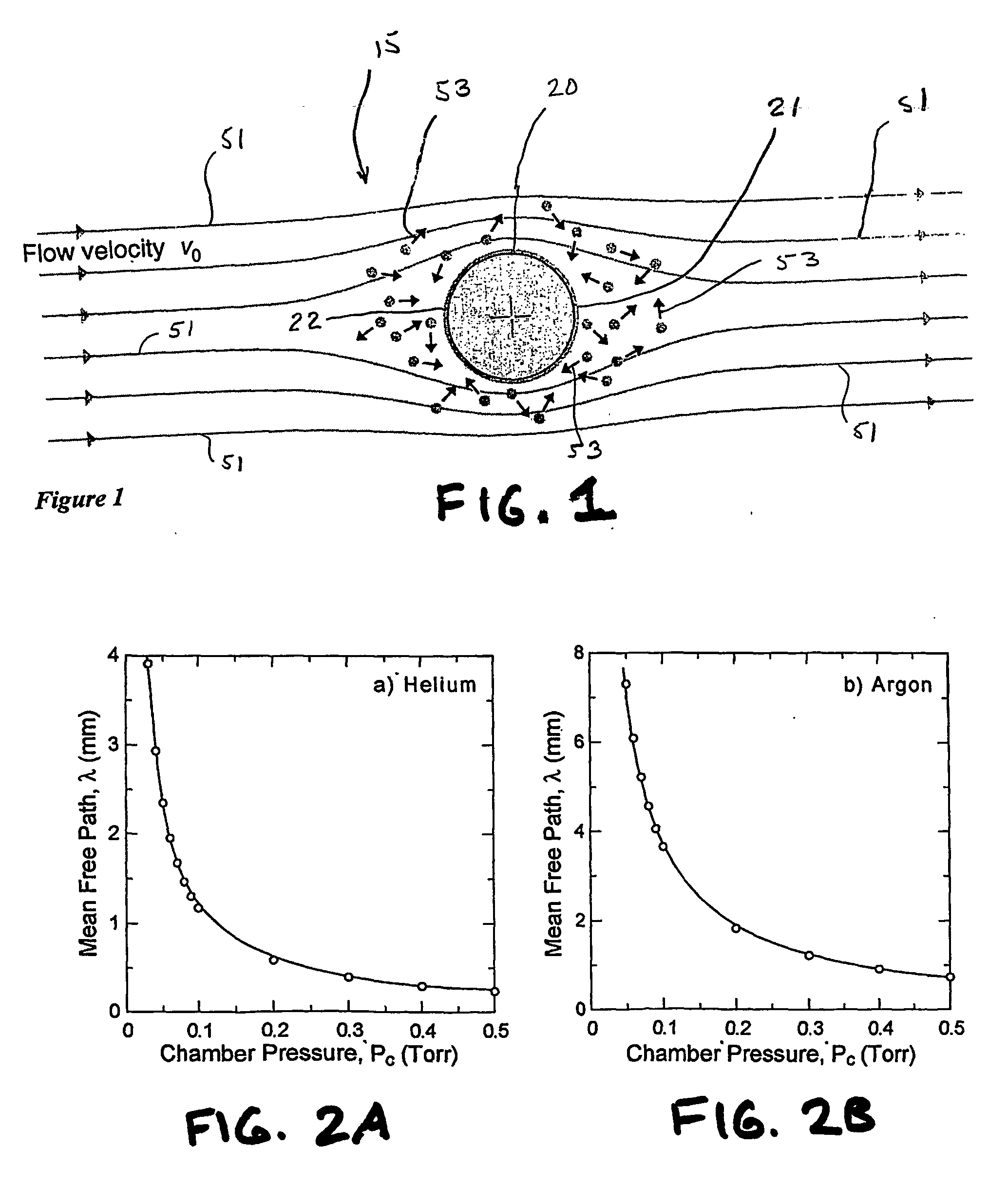
A direct vapor deposition (DVD) apparatus and method is taught, that provides a carrier gas flow entraining vapor atoms for the coating of regions on a substrate that are not in line-of-sight. The degree of non line-of-sight (NLOS) coating, hence thickness uniformity around the substrate is a sensitive function of the flow conditions. For a fixed background pressure in the region of deposition, an increase in the uniformity of the coating thickness is accomplished as the flow velocity is reduced. This improvement in uniformity is a result of an increase in the fraction of vapor atoms which deposit in NLOS positions on the substrate such as backside (21) of fiber (65) as indicated by vapor streamlines (51). Vapor impact width (VIW) is the width of the vapor flux impacting on some area of the fiber. Front side coating (FSC) width is the vapor width of atoms impacting on the substrate frontside (22).

Description

CROSS-REFERENCES TO RELATED APPLICATIONS [0001] The Present invention claims priority from U.S. Provisional Patent Application Ser. No. 60 / 375,552 filed Apr. 25, 2002, entitled “Apparatus and Method for Uniformly Coating onto Ligament Shaped Structures at High Rate,” the entire disclosure of which is hereby incorporated by reference herein in its entirety.US GOVERNMENT RIGHTS [0002] This invention was made with United States Government support under Grant No. N00014-00-1-0342, awarded by the Defense Advanced Research Projects Agency / Office of Naval Research. The United States Government has certain rights in the invention.FIELD OF TE INVENTION [0003] The present invention provides a method and an apparatus for efficiently applying a coating to a surface using a directed vapor deposition (DVD) approach, and more particularly applying a coating to the line of sight region as well as non-line of sight regions of the substrate at a high rate. BACKGROUND OF THE INVENTION [0004] The appli...

Claims


Application Information

Patent Timeline
IPC IPC(8): C23C14/04C23C14/30C23C14/54C23C16/00
CPCC23C14/04C23C14/046C23C14/542C23C14/30C23C14/228
Inventor HASS, DEREK D.QUEHEILLALT, DOUGLAS T.WADLEY, HAYDN N.G.
Owner UNIV OF VIRGINIA ALUMNI PATENTS FOUND
Learn More