
Receiver and method of operation thereof

a technology of a receiver and a channel, applied in the field of receivers, can solve the problems of limited channel capacity, inter-symbol interference, position-dependent fading, etc., and achieve the effect of reducing hardware costs

Inactive Publication Date: 2005-11-17
KONINKLIJKE PHILIPS ELECTRONICS NV
View PDF3 Cites 3 Cited by
  • Summary
  • Abstract
  • Description
  • Claims
  • Application Information

AI Technical Summary

Benefits of technology

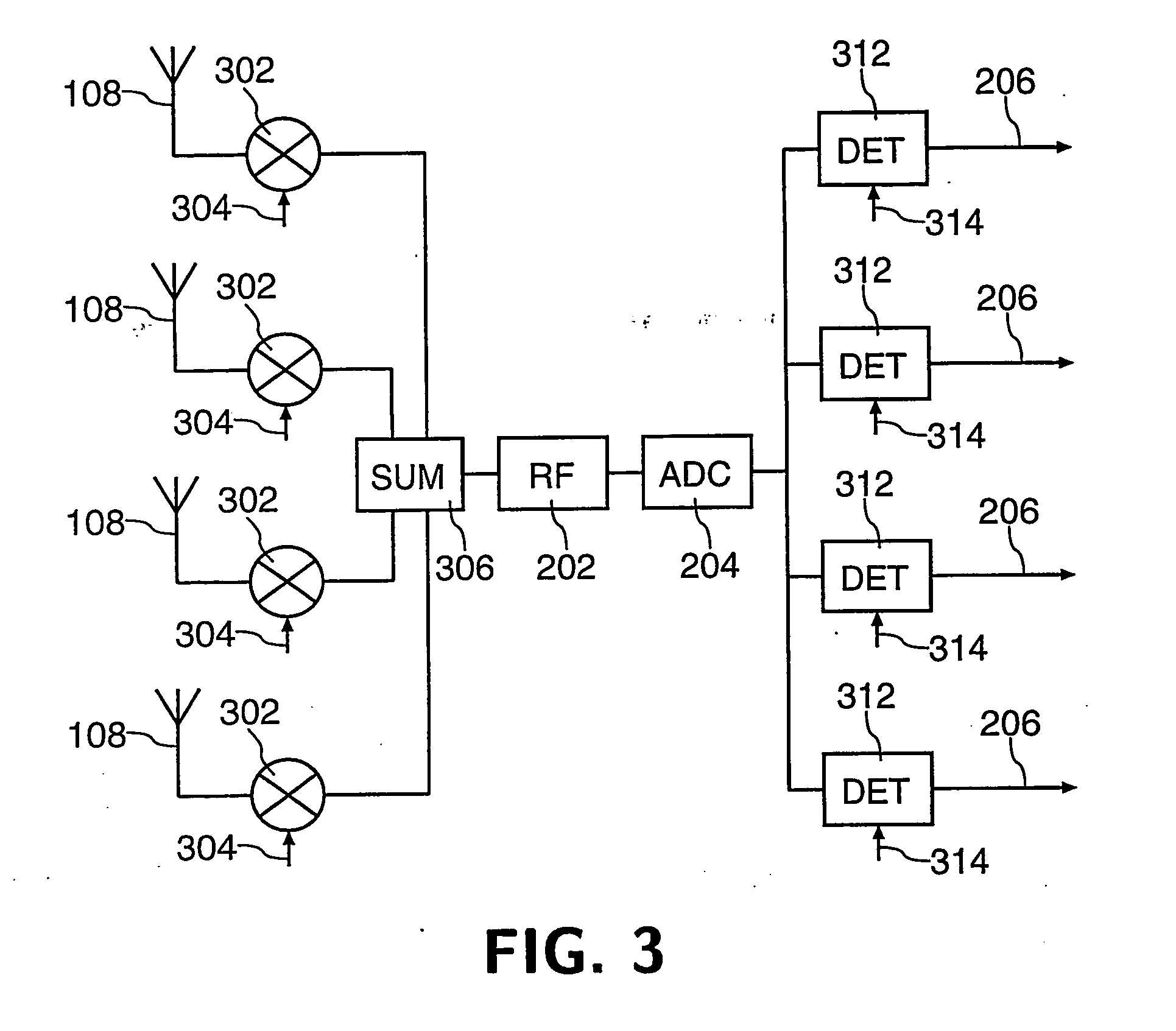
[0010] Application of the respective unique codes to each received signal enables a single frequency translation stage to be used to process a plurality of received signals, thereby both saving hardware and reducing the receiver's power consumption. In a preferred embodiment, the unique codes are orthogonal codes such as Walsh codes. The rate of the unique codes would typically need to be at least N times the symbol rate of the received signals, where N is equal to the number of antennas.
[0013] By means of the present invention it is possible to build a MIMO receiver having significantly reduced hardware costs compared to known receivers.

Problems solved by technology

Received signals from the paths may interfere constructively or destructively at the receiver (resulting in position-dependent fading).
Further, differing lengths of the paths, and hence the time taken for a signal to travel from the transmitter to the receiver, may cause inter-symbol interference.
However, a more useful way to view a MIMO system is that the capacity of the channel is limited by the number of statistically independent paths between the transmitter and receiver, caused by scatterers in the environment.
When designing a receiver for use in a MIMO system, significant extra expense is caused by the need for a separate RF (Radio Frequency) section, for each antenna to translate received signals from RF to base band.
However, a receiver implementing this technique still requires additional local oscillators in order to generate the required frequency offsets.

Method used


Image

  • Receiver and method of operation thereof
  • Receiver and method of operation thereof
  • Receiver and method of operation thereof

Examples


Embodiment Construction

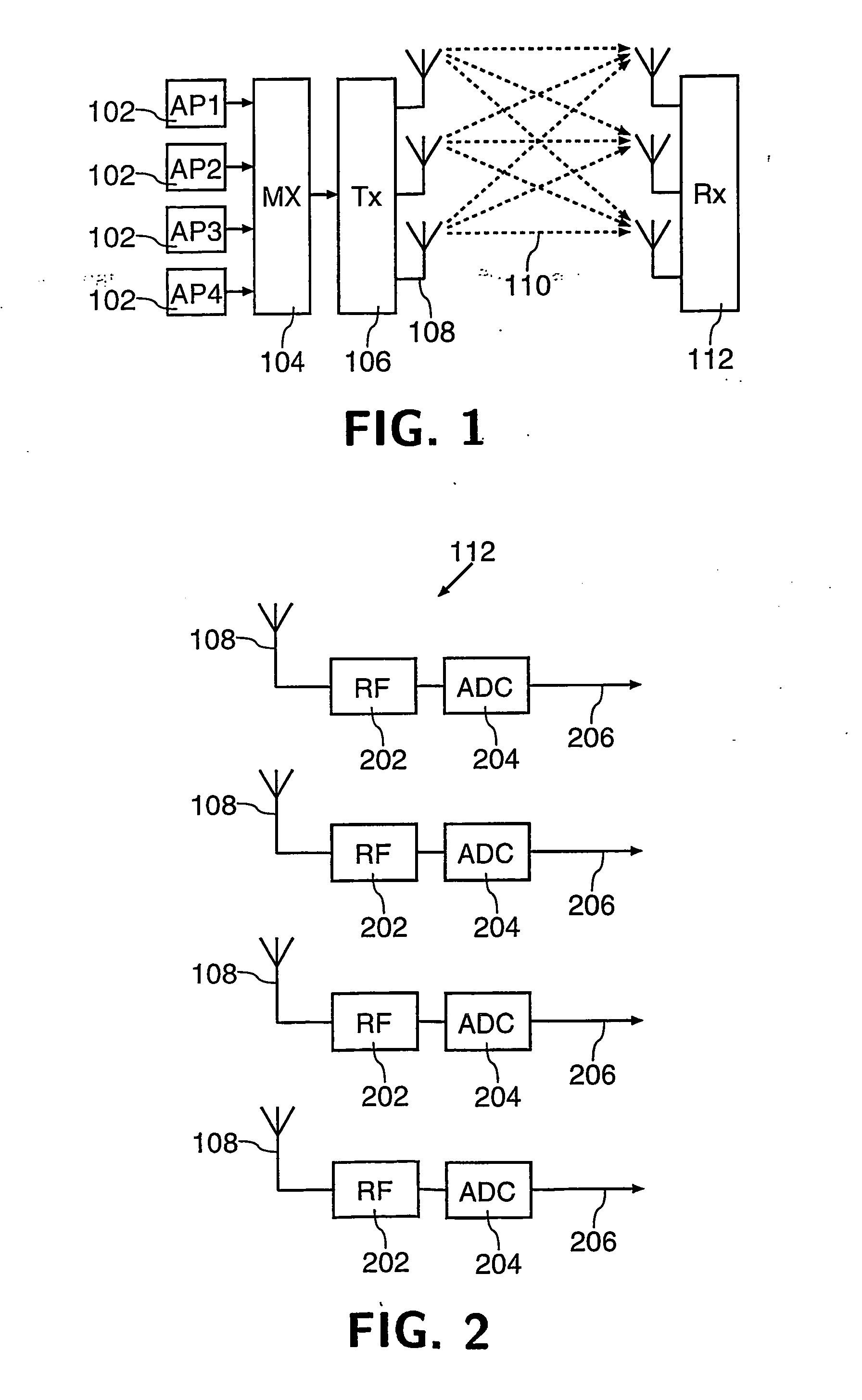
[0020]FIG. 1 illustrates a known MIMO radio system. A plurality of applications 102 (AP1 to AP4) generate data streams for transmission. An application 102 could also generate a plurality of data streams. The data streams are combined by a multiplexer (MX) 104 into a single data stream, which is supplied to a transmitter (Tx) 106. The transmitter 106 separates the data stream into sub-streams and maps each sub-stream to one or more of a plurality of transmit antennas 108.

[0021] Suitable coding, typically including Forward Error Correction (FEC), may be applied by the transmitter 106 before multiplexing. This is known as vertical coding, and has the advantage that coding is applied across all sub-streams. However, problems may arise in extracting the sub-streams since joint decoding is needed and it is difficult to extract each sub-stream individually. As an alternative each sub-stream may be coded separately, a technique known as horizontal coding which may simplify receiver operat...


PUM


Abstract

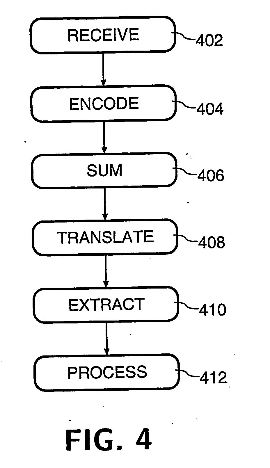
A receiver comprises a plurality of antennas (108) for receiving signals originally transmitted as a plurality of different signals, for example from a MIMO (Multi-Input Multi-Output) transmitter. The receiver includes a plurality of coders (302) for applying a respective unique code to each received signal and a summer (306) for combining the coded signals into a single signal which is then down-converted by a single frequency translation stage (202) and digitised. An output signal corresponding to each received signal is obtained by a plurality of detectors (312) with reference to the codes used by the coders. In a preferred embodiment, the unique codes are orthogonal codes such as Walsh codes. The receiver enables a single frequency translation stage to be used to process a plurality of received signals, thereby both saving hardware and reducing the receiver's power consumption.

Description

TECHNICAL FIELD [0001] The present invention relates to a receiver for receiving signals originally transmitted as a plurality of different signals, and to a method of operating the receiver. BACKGROUND ART [0002] In a typical communication system, radio signals travel from a transmitter to a receiver via a plurality of paths, each involving reflections from one or more scatterers. Received signals from the paths may interfere constructively or destructively at the receiver (resulting in position-dependent fading). Further, differing lengths of the paths, and hence the time taken for a signal to travel from the transmitter to the receiver, may cause inter-symbol interference. [0003] It is possible to take advantage of such a situation by the use of multiple antennas at both transmitter and receiver, enabling a plurality of different signals to be transmitted on the same frequency at the same time. Such a system is known as a Multi-Input Multi-Output (MIMO) system, whereby a data str...

Claims


Application Information

Patent Timeline
Patent Type & Authority Applications(United States)
IPC IPC(8): H04B1/707H04B7/04H04J11/00H04J99/00H04L1/06
CPCH04B1/707H04L1/06H04J13/0048H04B2201/70707H04B1/06H04B7/08
Inventor EVANS, DAVID H.KHATRI, BHAVIN S.RAYNES, DEBORAH L.
Owner KONINKLIJKE PHILIPS ELECTRONICS NV
Learn More