
Magnetic head slider having protrusion-compensated air bearing surface design

Inactive Publication Date: 2005-11-17
WESTERN DIGITAL TECH INC
View PDF30 Cites 8 Cited by
  • Summary
  • Abstract
  • Description
  • Claims
  • Application Information

AI Technical Summary

Benefits of technology

[0009] It is an advantage of the magnetic head slider of the present invention that heat caused protrusion of the central pad has a minimal effect upon the air bearing gap between the slider and the disk surface.
[0010] It is another advantage of the magnetic head slider of the present invention that the flying characteristics of the slider are affected by the protrusion of the central pad, such that the flying height of the slider is increased when protrusion occurs.
[0011] It is a further advantage of the magnetic head slider of the present invention that protrusion of the central pad creates an increase in the flying height of the slider, such that the air bearing gap is not substantially affected by the protrusion.
[0012] It is an advantage of the hard disk drive of the present invention that it includes a magnetic head slider wherein the heat caused protrusion of the central pad has a minimal effect upon the air bearing gap between the slider and the disk surface.
[0013] It is another advantage of the hard disk drive of the present invention that it includes a magnetic head slider wherein the flying characteristics of the slider are affected by the protrusion of the central pad, such that the flying height of the slider is increased when protrusion occurs.
[0014] It is a further advantage of the hard disk drive of the present invention that it includes a magnetic head slider wherein the protrusion of the central pad creates an increase in the flying height of the slider, such that the air bearing gap is not substantially affected by the protrusion.

Problems solved by technology

This protrusion substantially reduces the air bearing gap at the protrusion location and increases the likelihood that unwanted physical contact will occur between the rotating disk and the protruding portions of the slider, thereby causing damage to the disk surface or to the protruding magnetic head components of the slider.

Method used


Image

  • Magnetic head slider having protrusion-compensated air bearing surface design
  • Magnetic head slider having protrusion-compensated air bearing surface design
  • Magnetic head slider having protrusion-compensated air bearing surface design

Examples


Embodiment Construction

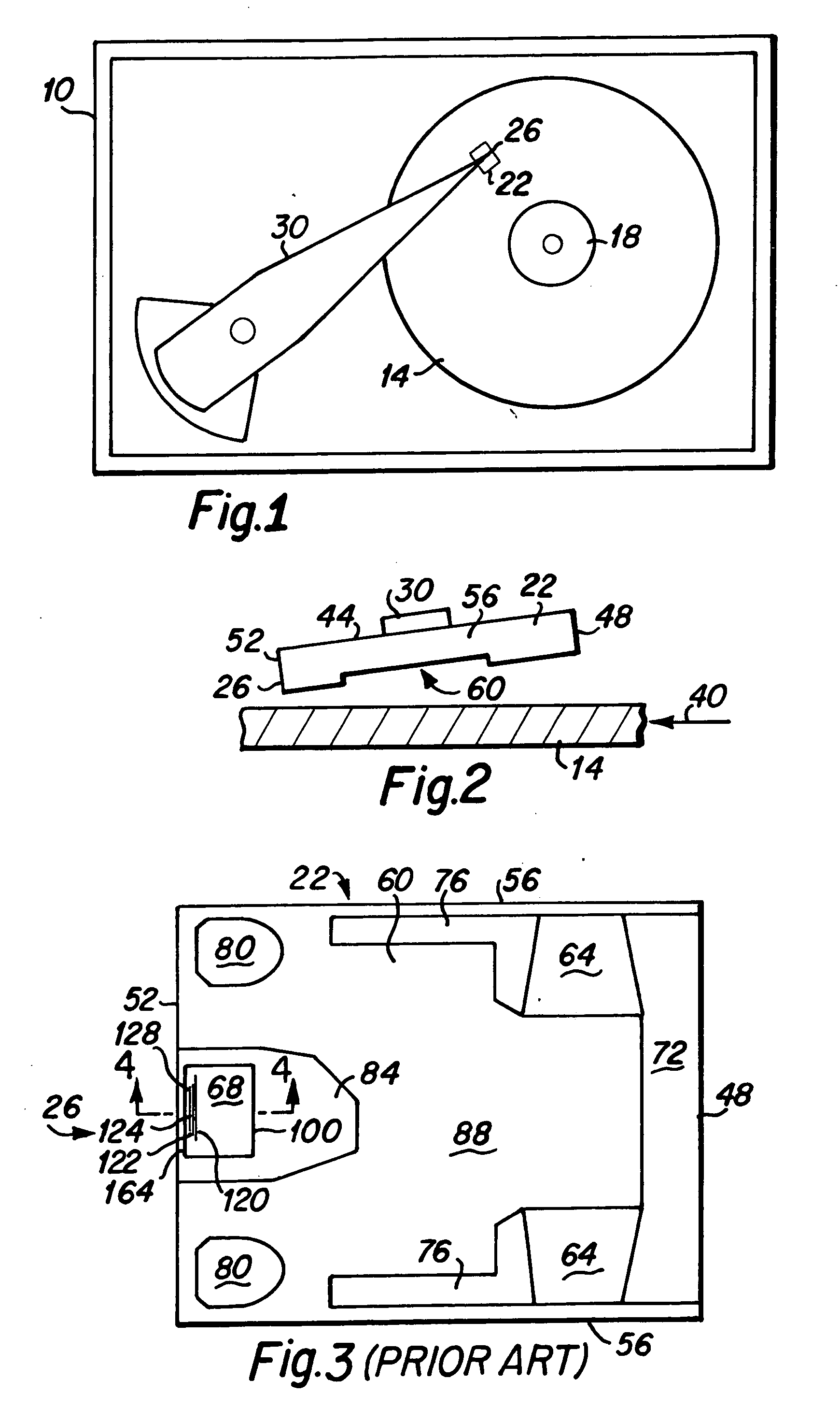
[0024] A simplified top plan view of a typical hard disk drive 10 which includes a magnetic head of the present invention is presented in FIG. 1. As depicted therein, at least one hard disk 14 is rotatably mounted upon a motorized spindle 18. A slider 22, having a magnetic head 26 disposed thereon, is mounted upon an actuator arm 30 to fly above the surface of each rotating hard disk 14, as is well known to those skilled in the art. The present invention includes improved features for such magnetic head sliders.

[0025]FIG. 2 is a side elevational view depicting a magnetic head slider 22 disposed above the surface of a rotating disk 14; the direction of disk rotation is indicated by the arrow 40. The slider includes a top surface 44 that is engaged to the actuator arm 30, a front leading edge 48, a trailing rear edge 52, two side edges 56 (one of which is shown in FIG. 2), and a lower surface 60 that is commonly referred to as the air bearing surface (ABS) of the slider, and which is...


PUM


Abstract

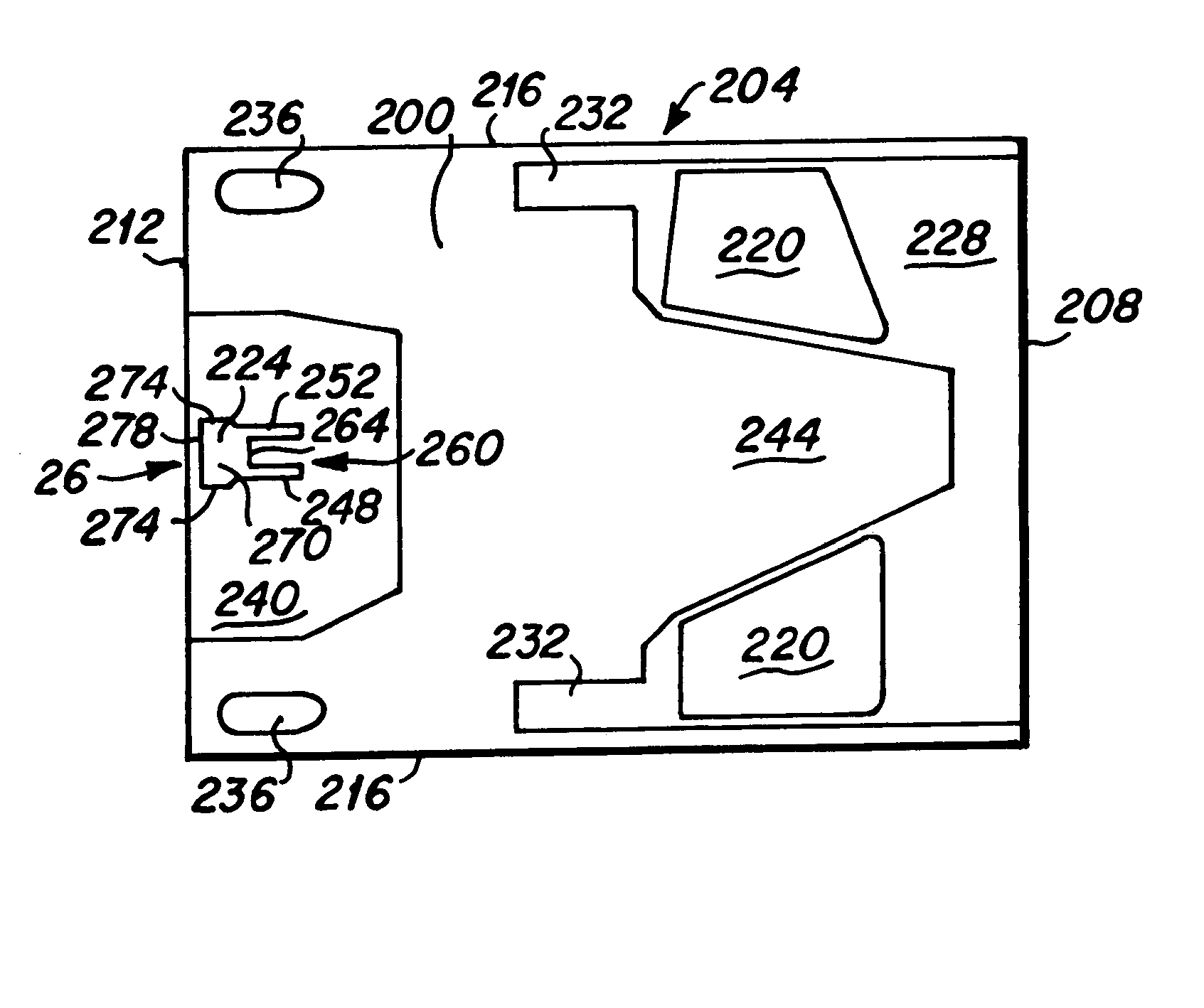
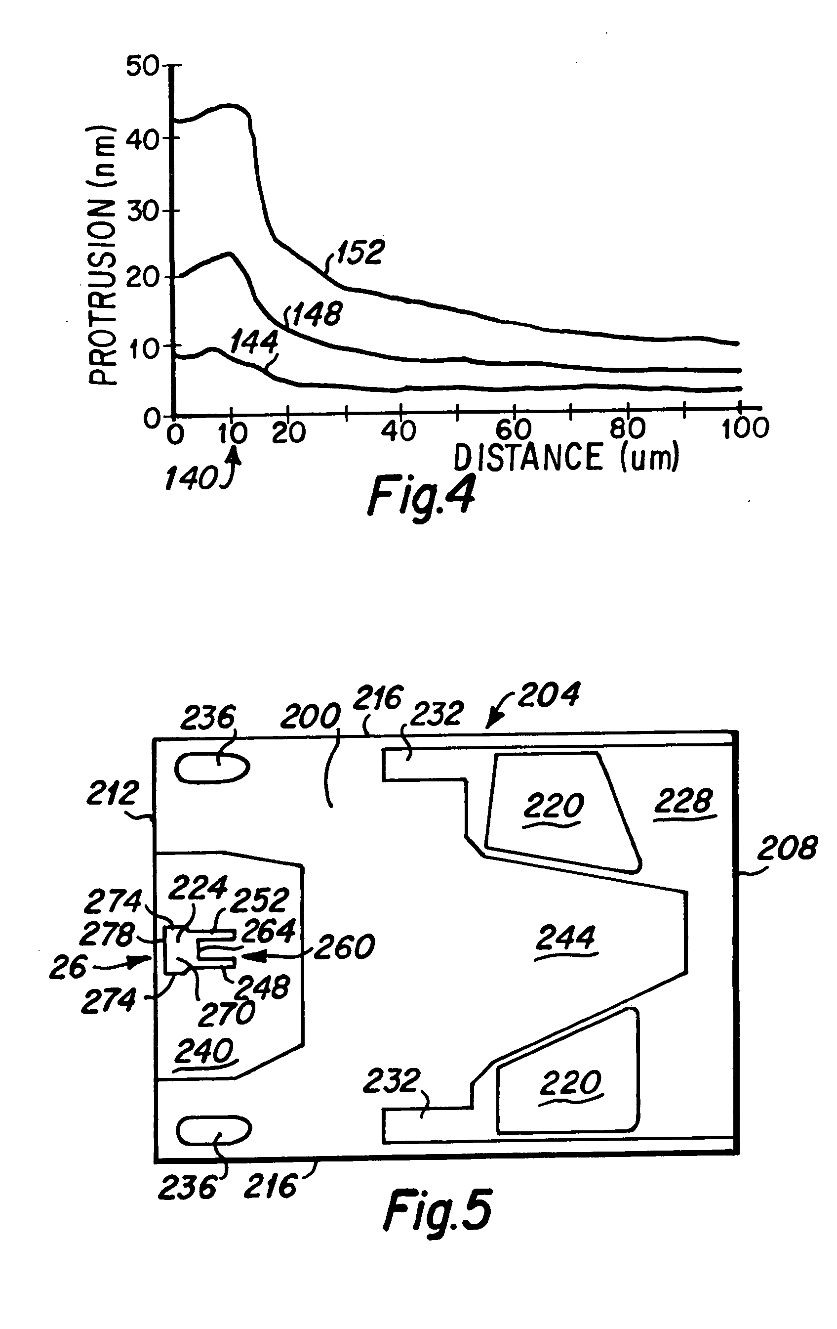
A magnetic head slider including a central pad that is disposed at the trailing edge of the slider and designed to increase the flying height of the slider in response to heat induced protrusion of the head elements. The central pad of the present invention includes a body portion and two arm portions which project forwardly from a leading edge of the body portion, such that the leading portion of the central pad is formed with a generally U-shaped profile. The length of the arm members is preferably from approximately ¼ of the total length of the central pad to approximately ¾ of the total length of the central pad.

Description

BACKGROUND OF THE INVENTION [0001] 1. Field of the Invention [0002] The present invention relates generally to air bearing surface designs for sliders including magnetic heads for hard disk drives, and more particularly to a slider air bearing surface that is designed to adjust its fly height above a disk surface in response to protrusion of portions of the air bearing surface caused by heat generated within the magnetic head. [0003] 2. Description of the Prior Art [0004] As is well known to those skilled in the art, standard hard disk drives include magnetic media disks that are rotatably mounted upon a motorized spindle. A magnetic head slider is mounted upon an actuator arm such that the slider flies above the surface of the disk on the moving air film associated with the rotating disk surface. The moving air film is generally referred to as an air bearing, and the flying height of the slider is generally referred to as the air bearing gap. [0005] In the continual quest for highe...

Claims


Application Information

Patent Timeline
IPC IPC(8): G11B5/60
CPCG11B5/6005
Inventor NIKITIN, VLADIMIRRUIZ, OSCAR JAIME
Owner WESTERN DIGITAL TECH INC
Learn More