
Dynamic audio control circuit and method

a technology of dynamic audio control and circuit, applied in the field of audio systems, can solve the problems of deprived audio device operator of the ability to dynamically adjust or change frequency equalization subbands, neither automatically nor dynamically adjust or change equalizers

Inactive Publication Date: 2005-11-10
MOTOROLA INC
View PDF10 Cites 51 Cited by
  • Summary
  • Abstract
  • Description
  • Claims
  • Application Information

AI Technical Summary

Benefits of technology

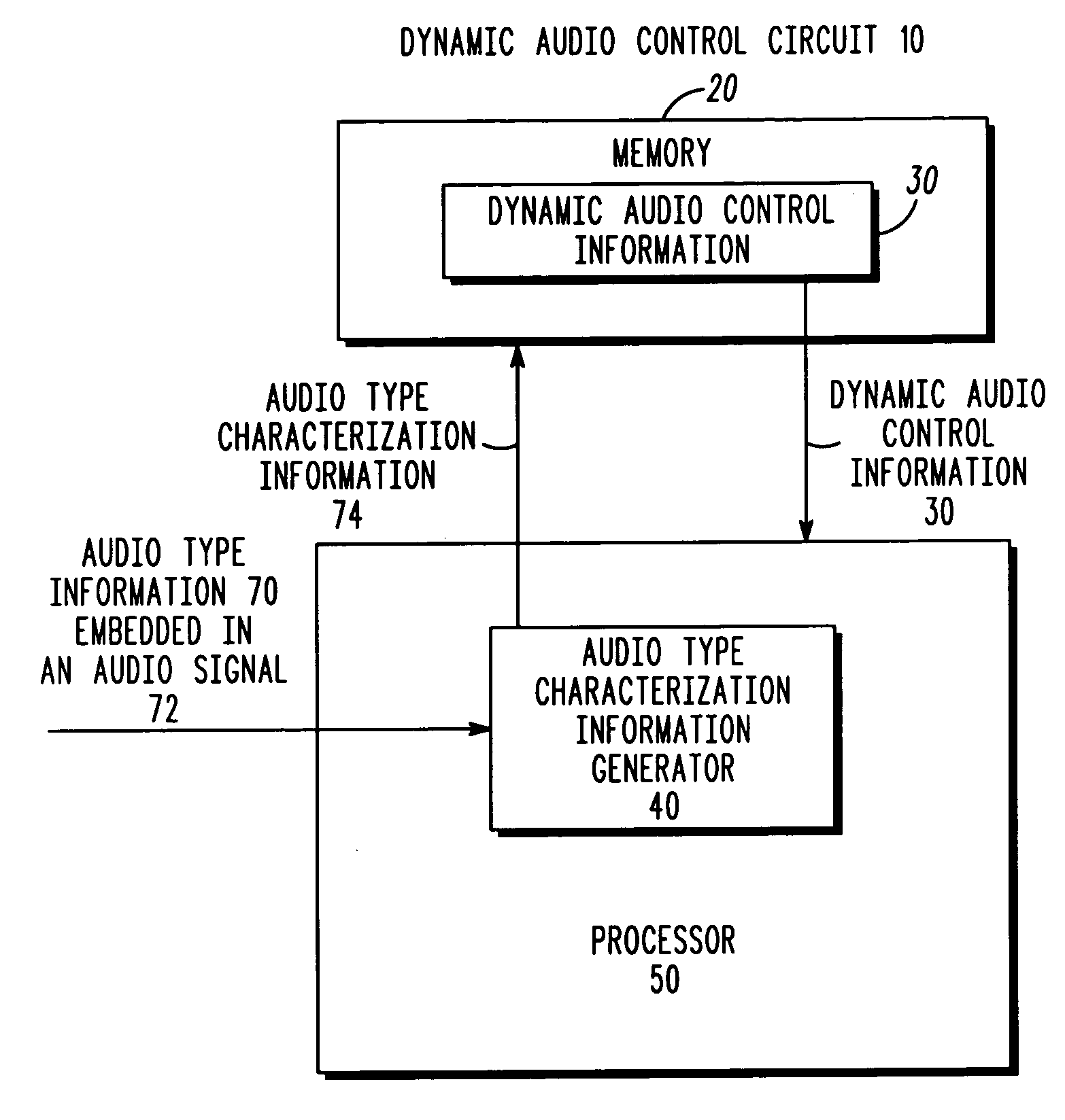
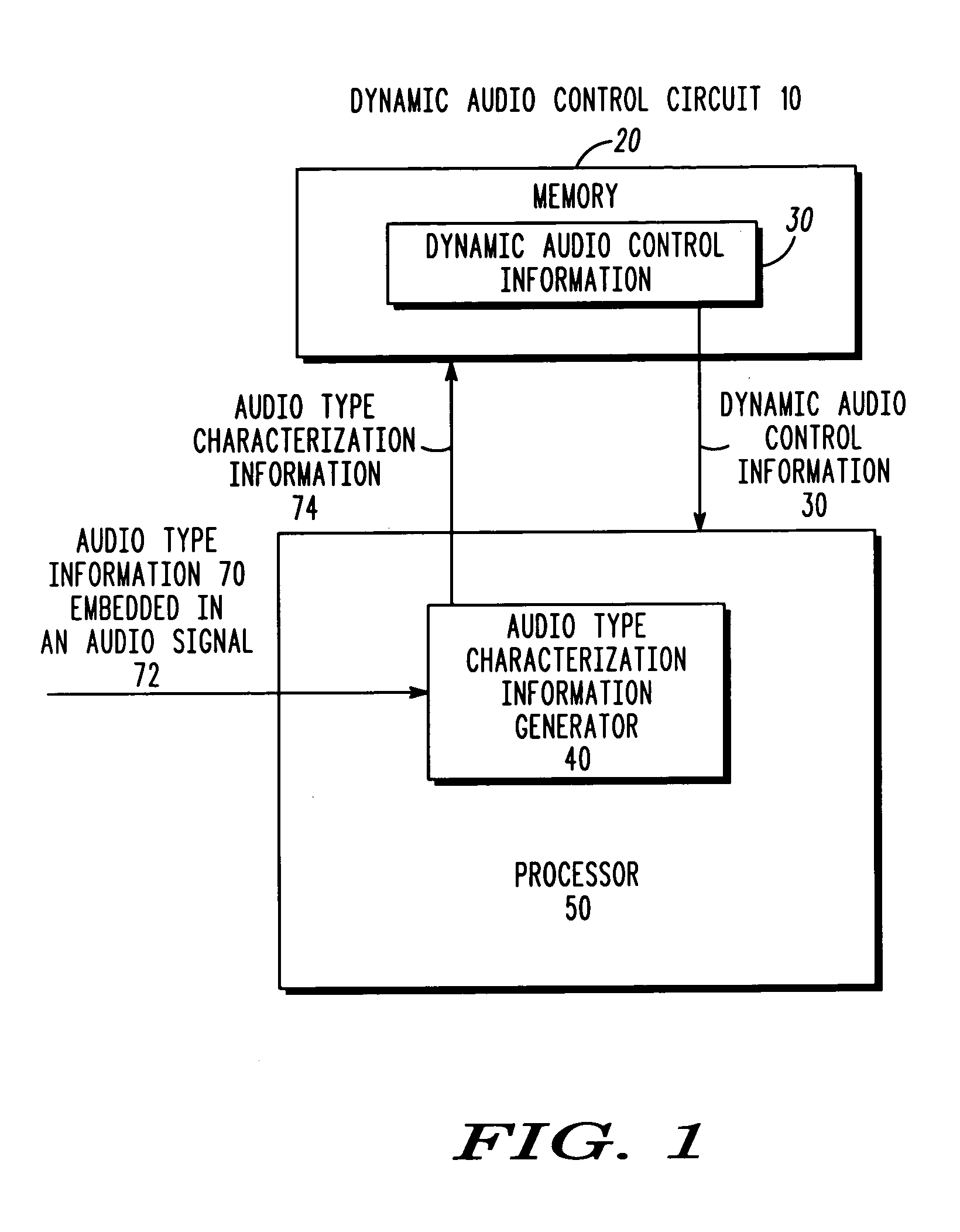
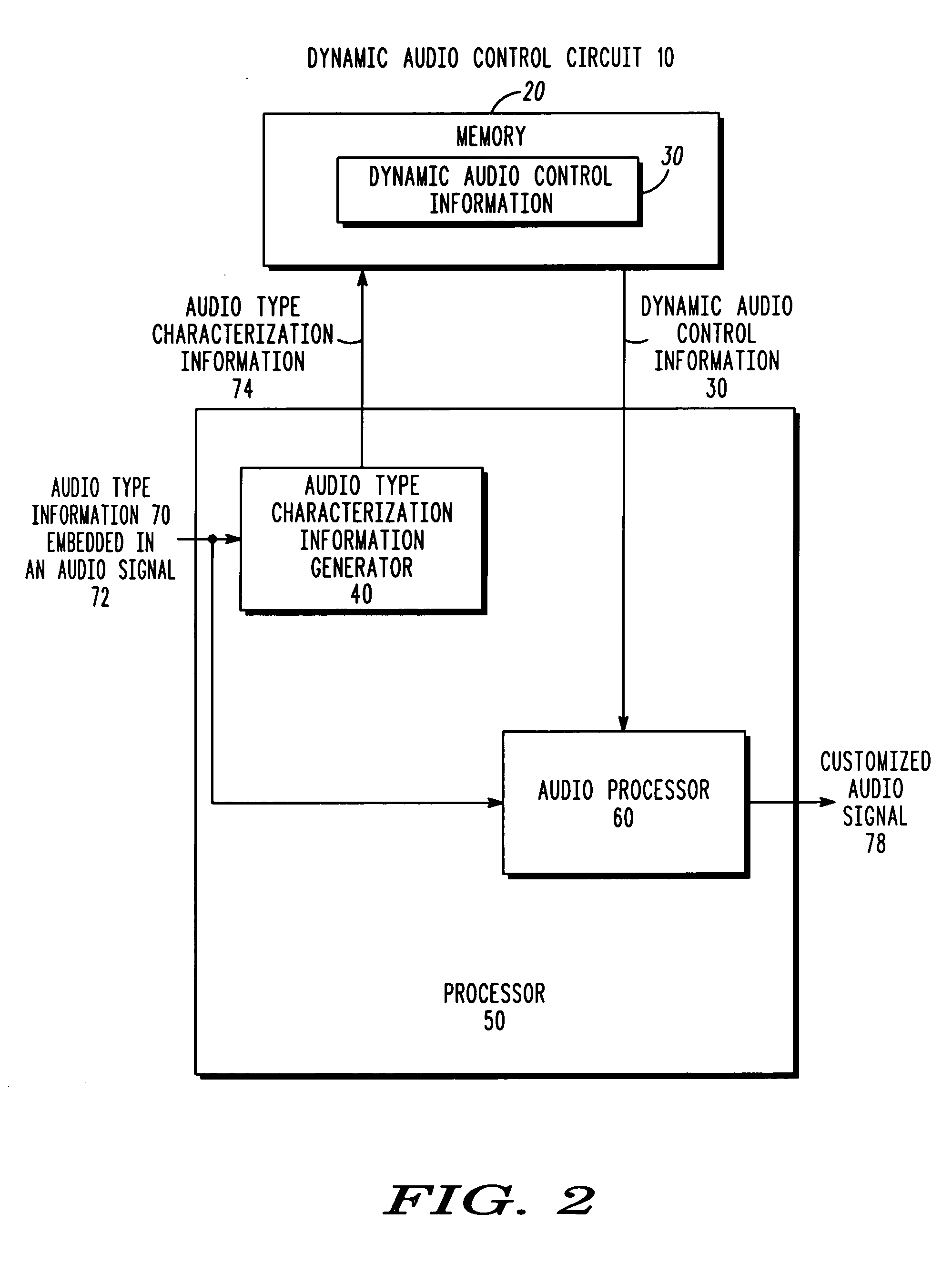
The present invention relates to a dynamic audio control circuit and method that can automatically adjust the audio parameters of an audio system based on the type of audio program being played. This allows for customization of the audio signal without user intervention, as the audio type information or audio information embedded in the audio signal is detected and used to adjust the audio parameters. The dynamic audio control circuit can automatically change the audio signal parameter settings in real-time during, for example, a song or a news broadcast if a change in the audio type information or audio information is detected. This results in a more customized playback experience for the user, as the audio parameters can be adjusted according to the type of audio program being played.

Problems solved by technology

For example, if, while listening to a tape of a disco song, one particular equalization setting is desired, then the equalizer does not automatically nor dynamically adjust or change the frequency equalization subbands if the tape plays a different category of music, such as classical music.
Therefore, these types of signal equalization selector devices only involve the use of fixed equalization networks, thus depriving the operator of the audio device the ability to dynamically change the amount of equalization to his or her own personal taste for each of the different types of audio program signals that may be selected.

Method used


Image

  • Dynamic audio control circuit and method
  • Dynamic audio control circuit and method
  • Dynamic audio control circuit and method

Examples


Embodiment Construction

[0011] A dynamic audio control circuit and method receives audio type information or audio information embedded in an audio signal and in response dynamically adjusts the audio signal without user intervention. The dynamic audio control circuit may adjust equalization and time delay parameters based on, for example, an audio spectrum analysis of the received audio information such as music or any other suitable audio program embedded in the audio signal. According to one embodiment, the audio type information may be, for example, descriptive information such as station and program information transmitted along with a standard radio, television or satellite broadcast. According to another embodiment, the audio type information may be equalization and time delay settings associated with the audio signal.

[0012] Among other advantages, the dynamic audio control circuit adapts to the varying audio information or varying audio type information embedded in the audio signal. In response to...


PUM


Abstract

A dynamic audio control circuit (10) and method receives audio type information (70) or audio information (670) embedded in an audio signal (72, 672) and in response dynamically adjusts the audio signal (72, 672) without user intervention. The dynamic audio control circuit (10) may adjust equalization and time delay parameters based on, for example, an audio spectrum analysis of the received audio information (670) embedded in the audio signal (672). According to one embodiment, the audio type information (70) may be, for example, descriptive information such as station and program information transmitted along with a standard radio, television or satellite broadcast. According to another embodiment, the audio type information (70) may be equalization and time delay settings associated with the audio signal (72). The audio characterization information (74, 674) may be used to characterize the audio signal (72, 672) in order to provide a basis for adjusting or customizing the audio signal (72, 672) to the taste of the user.

Description

FIELD OF THE INVENTION [0001] The invention relates generally to audio systems and, more particularly, to audio customization circuits and methods. BACKGROUND OF THE INVENTION [0002] Audio equalizers provide for the separate manual adjustment of the relative emphasis of multiple frequency subbands of a selected audio signal so that the audio frequency response of an audio system can be operator-adjusted to suit the operator's personal preference. These audio equalizers implement different signal equalizations for different audio signal program selections by selectively coupling equalization circuits into a selected audio signal path in accordance with a selected audio program signal. For example, a radio with an audio equalizer can be utilized to provide a desired audio frequency equalization for its audio input. As a user selects a signal source such as, for example, either AM, FM or tape player modes of operation, the signal could be equalized based on the selection of the AM, FM ...

Claims


Application Information

Patent Timeline
Patent Type & Authority Applications(United States)
IPC IPC(8): G06F17/00H04H1/00H04H20/31H04H60/13H04H60/37H04H60/44H04H60/65
CPCH04H20/31H04H60/13H04H60/65H04H60/44H04H60/37
Inventor BYCHOWSKY, MICHAEL W.PETERSON, DAVID P.SEICK, RYAN E.
Owner MOTOROLA INC
Learn More