
Wire-cut electric discharge machine

a wire-cutting machine and electric discharge technology, applied in the direction of electrical-based machining apparatus, metal-working apparatus, manufacturing tools, etc., can solve the problem that the variation of the wire tension attributable to any other factors cannot be fully reduced, and achieve the effect of satisfactory linearity adjustable magnitude of the applied tension, and good machining

Inactive Publication Date: 2005-11-03
FANUC LTD
View PDF8 Cites 4 Cited by
  • Summary
  • Abstract
  • Description
  • Claims
  • Application Information

AI Technical Summary

Benefits of technology

[0016] Accordingly, the object of the present invention is to effectively restrain the tension variation of a wire that is caused on the wire supply side of brake rollers, improve the linearity of the wire tension variation, cope with a wide range of tension variation, and adjust the tension variation restraint characteristics.
[0028] According to the present invention arranged in this manner, the variation of the wire tension caused on the wire supply side of the brake rollers can be restrained effectively. Further, the linearity of the wire tension variation can be improved, and a wide range of variation can be coped with. Furthermore, the tension vibration restraint characteristics can be regulated by adjusting the magnitude of the applied tension.

Problems solved by technology

Thus, there is a problem that variations of the wire tension that are attributable to any other factors cannot be fully reduced.

Method used


Image

  • Wire-cut electric discharge machine
  • Wire-cut electric discharge machine
  • Wire-cut electric discharge machine

Examples


Embodiment Construction

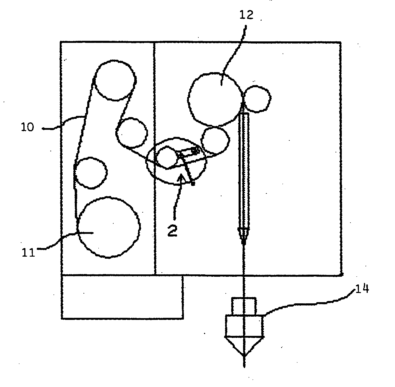
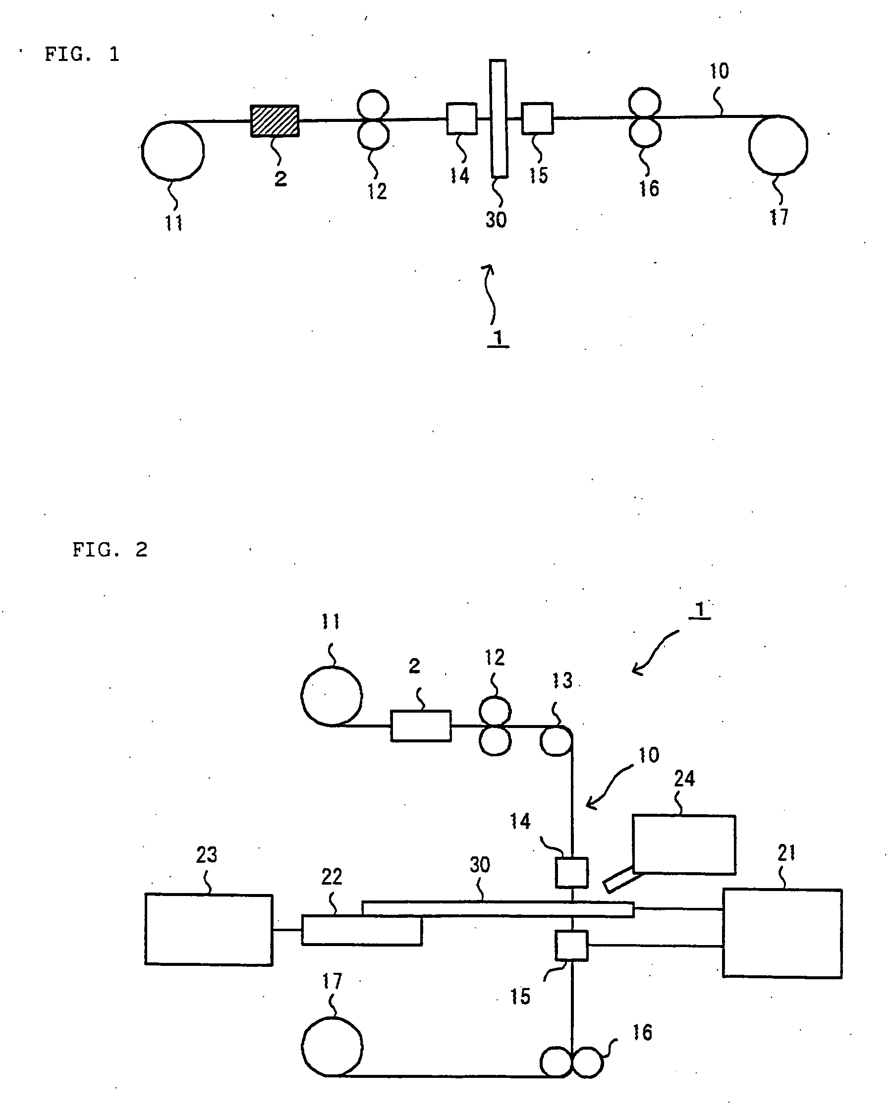
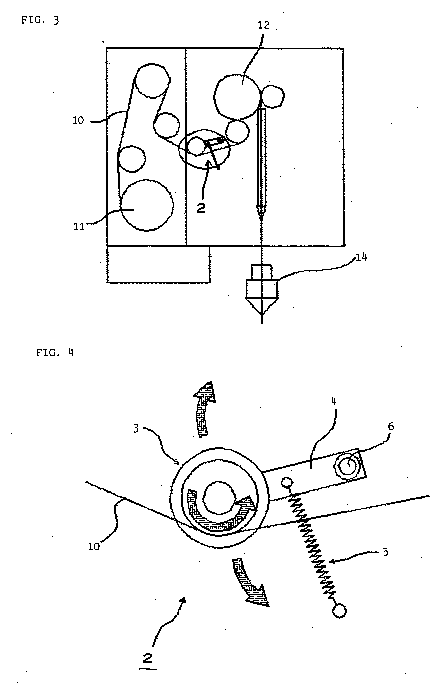
[0038]FIG. 1 is a diagram for illustrating an outline of a wire-cut electric discharge machine according to the present invention. The wire-cut electric discharge machine 1, like the prior art example shown in FIG. 8, comprises a wire running system, which includes a wire bobbin 11, brake rollers 12, upper wire guide 14, lower wire guide 15, take-up rollers 16, and take-up bobbin 17. These elements of the system supply and wind up a wire in the order named. In this wire running system, a device (wire tension variation reduction device) 2 for reducing the variation of the wire tension is provided between the wire bobbin 11 and the brake rollers 12. The wire tension variation reduction device 2 serves to restrain the variation of the wire tension that is caused on the wire supply side of the brake rollers 12.

[0039] If the wire tension fluctuates on the wire supply side of the brake rollers 12 in FIG. 1, owing to variation of the rotational speed of the wire bobbin 11 or the friction ...


PUM

PropertyMeasurementUnit
Elasticityaaaaaaaaaa
Tensionaaaaaaaaaa

Abstract

A wire-cut electric discharge machine comprises a wire running system, in which a wire is run through a wire bobbin, brake rollers, a wire guide, and a wire take-up device in the order named. As a device for reducing the variation in wire tension is arranged between the wire bobbin and the brake rollers in the wire running system, variation of the wire tension that is caused on the wire supply side of the brake rollers can be restrained effectively.

Description

BACKGROUND OF THE INVENTION [0001] 1. Field of the Invention [0002] The present invention relates to a wire-cut electric discharge machine, and more particularly, to a structure for reducing vibration of a wire electrode. [0003] 2. Description of the Related Art [0004] When the tension of a wire in a wire-cut electric discharge machine varies to cause the wire to vibrate, the machining accuracy of the machine lowers, so that the surface accuracy and straightness accuracy of a workpiece lower. Conventionally, in order to restrain such wire vibration, machining conditions, such as current, voltage, etc., and set machining speed are adjusted to apply tension to the wire. In a known method for applying tension to the wire, a roller of a wire running system is made reluctant to rotate as its shaft is subjected to friction. By doing this, the roller is braked so that the wire is tensioned. [0005] If the wire vibration is reduced by applying tension to the wire, the rotational speed or fri...

Claims


Application Information

Patent Timeline
IPC IPC(8): B23H7/10
CPCB23H7/104B23H7/10
Inventor KITA, YUKITAKAYAMA, YUSHIMAKINO, YOSHINORI
Owner FANUC LTD
Learn More