
Correction parameter determination system

Active Publication Date: 2005-10-27
III HLDG 6
View PDF7 Cites 3 Cited by
  • Summary
  • Abstract
  • Description
  • Claims
  • Application Information

AI Technical Summary

Benefits of technology

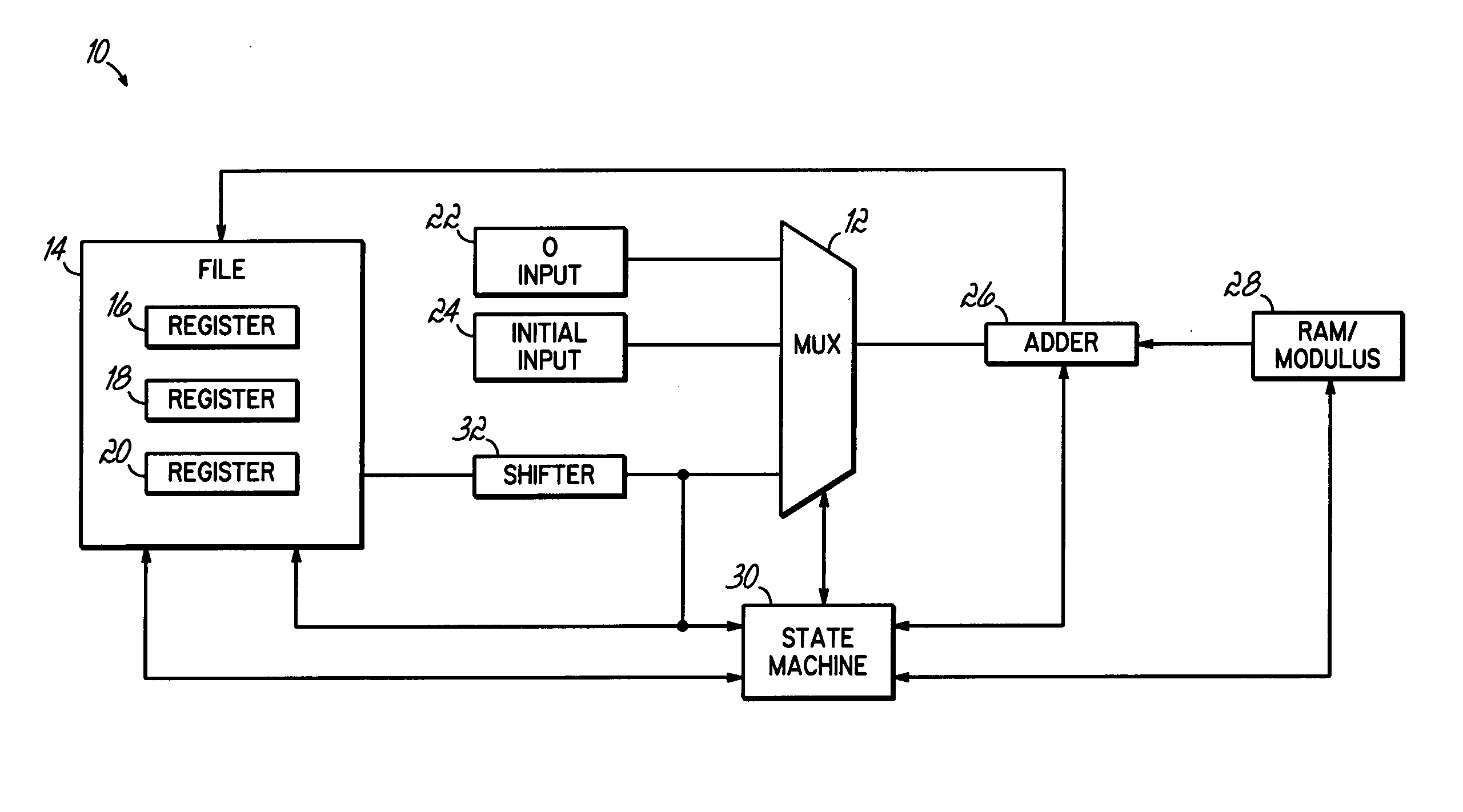
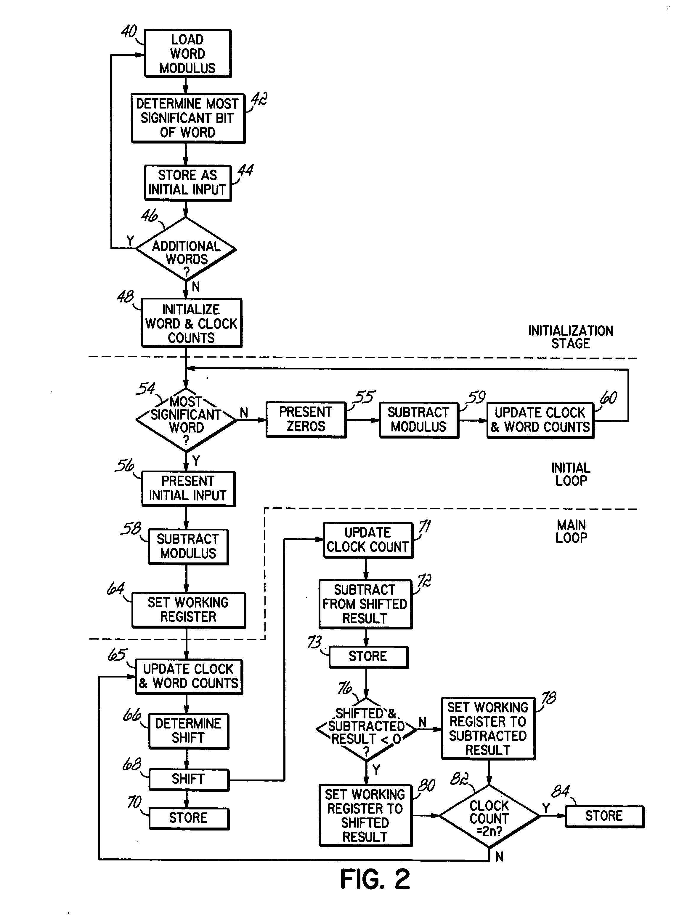
[0008] The invention addresses these and other problems associated with the prior art by in one aspect providing a circuit arrangement and method that performs a plurality of shift / compare operations on a working register that has an initial value greater than a modulus value. For instance, the initial input may be selected to be the smallest exponent of 2 that is greater than the modulus (i.e., in binary, a binary “1” value left shifted to one position past the most significant bit of the modulus). Such an initial setting can reduce the number of required loop iterations and accelerate the parameter's determination.
[0009] Moreover, consistent with another aspect of the invention, the working register may be shifted by more than one position in connection with a shift / compare operation in order to further reduce loop iterations. Further processing accelerations realized by the present invention include conducting subtraction and shifting operations in parallel. During each shift / compare operation, or loop iteration, the modulus value may be subtracted from the working register to yield a subtracted result, while the result of a shifting operation is conducted and stored separately from the subtracted result. As such, either of the two stored results may serve readily as input to the next iteration of the loop, following a comparison, without the delays that plague conventional processing.
[0010] In so doing, the concepts of the present invention individually and conjunctively reduce processing times associated with error correction parameter determination, while further reducing costs associated with purchase and assembly of logic gates and other hardware.

Problems solved by technology

However, the size of the modulus, N, which can be on the order of thousands of bits in length, can burden even large processors.
Alternatively, hardware circuit implementations that use dedicated gates to avoid the long delays of software are subject to their own timing issues.
The tradeoff for the reduced size of subtraction circuitry is that each loop iteration requires multiple clock cycles to handle each subtraction operation.

Method used


Image

  • Correction parameter determination system
  • Correction parameter determination system
  • Correction parameter determination system

Examples


Embodiment Construction

[0016] Error correction determination for Montgomery modulation that is consistent with the invention may incorporate one or all of three concepts that provide substantial advantages over conventional parameter calculation techniques. The first concept applies to initializing an initial value for processing in a shift / compare operation, or loop iteration of an error correction circuit. This contrasts with conventional parameter calculation operations that shift the working register from a small initial value, e.g. “1,” which typically requires approximately n iterations of a loop to be performed before the modulus is ever subtracted from a working value.

[0017] As an example, consider an exemplary operation where the modulus is a number with a most significant bit of 945. A conventional operation, beginning with “1” and shifting / comparing by one register place for each iteration, would require 945 loop iterations before the working register has a most significant bit that is greater...


PUM


Abstract

An circuit arrangement and method for reducing the number of processing loops needed to generate an error correction parameter used in the Montgomery method. An initial input to a processing loop is set to a value equal to the modulus, left shifted one register position. Values of the working register are shifted multiple positions during a single loop iteration, and a shifted result is subtracted and compared to zero to determine subsequent contents of the working register.

Description

FIELD OF THE INVENTION [0001] The invention is generally related to circuits and systems for performing modular exponentiations of large numbers, and more particularly, to circuits and systems for production of an error correction parameter associated with Montgomery modular multiplication. BACKGROUND ART [0002] The demand for secure information continues to drive improvements relating to cryptology. Modular exponentiation, and more particularly, the Montgomery algorithms, remains fundamental to the encryption and decryption of confidential, authenticated data used in Internet and electronic commerce. Montgomery modulation generally exploits properties and interrelations of very large numbers to avoid working with the numbers, themselves. Accordingly, dedicated programming and hardware for implementing Montgomery processes have been developed to achieve the repeated multiplications required for modular exponentiation in a faster and more efficient manner. [0003] Calculation of an er...

Claims


Application Information

Patent Timeline
IPC IPC(8): G06F11/00
CPCG06F7/728
Inventor HARMON, TIM
Owner III HLDG 6
Learn More