Crossbar spinal prosthesis having a modular design and related implantation methods

Inactive Publication Date: 2005-10-27
FACET SOLUTIONS
View PDF99 Cites 242 Cited by
  • Summary
  • Abstract
  • Description
  • Claims
  • Application Information

AI Technical Summary

Benefits of technology

[0028] In yet another embodiment, there is provided a crossbar that is adaptable and configured for placement joining two cephalad elements, or alternatively, two caudal elements. Additional crossbar embodiments provide different attachment mechanism and locations between the elements. Moreover, additional embodiments provide adaptability of one or more of one or more cephalad elements, one or more caudal elements, and / or one or more crossbar elements.
[0036] In additional alternative embodiments, there are provided different components, methods and configurations to provide improved tissue shielding capabilities, such as for example, placing the selected or basing the selection of the modular components on reducing the occurrence of tissue being caught in the prosthesis. In one specific embodiment, the relative positions are modified such as by reversing the caudal and the cephalad bearings to protect tissue from getting caught in the contacting arms.

Problems solved by technology

In many cases, the pain severely limits a person's functional ability and quality of life.
Through disease or injury, the laminae, spinous process, articular processes, or facets of one or more vertebral bodies can become damaged, such that the vertebrae no longer articulate or properly align with each other.
This can result in an undesired anatomy, loss of mobility, and pain or discomfort.
For example, the vertebral facet joints can be damaged by either traumatic injury or by various disease processes.
The damage to the facet joints often results in pressure on nerves, also called “pinched” nerves, or nerve compression or impingement.
The result is pain, misaligned anatomy, and a corresponding loss of mobility.
These traditional treatments are subject to a variety of limitations and varying success rates.
None of the described treatments, however, puts the spine in proper alignment or returns the spine to a desired anatomy or biomechanical functionality.
In addition, stabilization techniques hold the vertebrae in a fixed position thereby limiting a person's mobility and can compromise adjacent structures as well.
Prosthesis customization to patient specific disease state and anatomy are among the challenges faced when implanting a prosthesis.
Current prostheses designs have not provided prosthesis systems having modular designs that are configurable and adaptable to patient specific disease state and anatomy.

Method used


Image

  • Crossbar spinal prosthesis having a modular design and related implantation methods
  • Crossbar spinal prosthesis having a modular design and related implantation methods
  • Crossbar spinal prosthesis having a modular design and related implantation methods

Examples


first embodiment

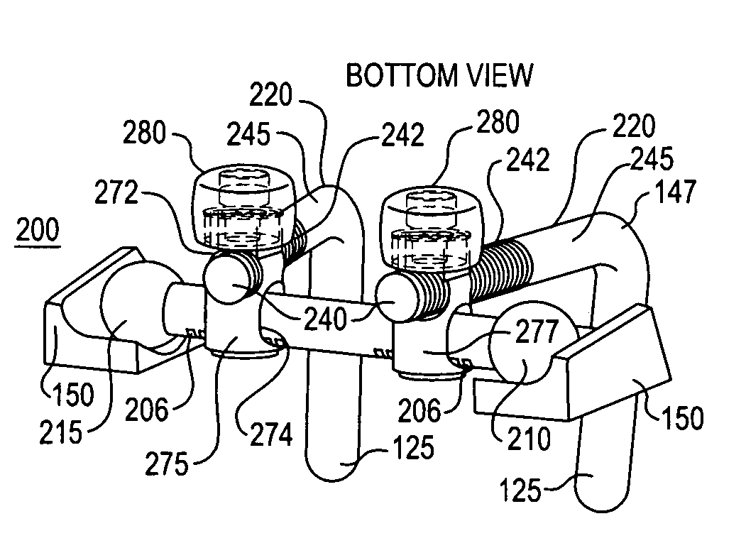
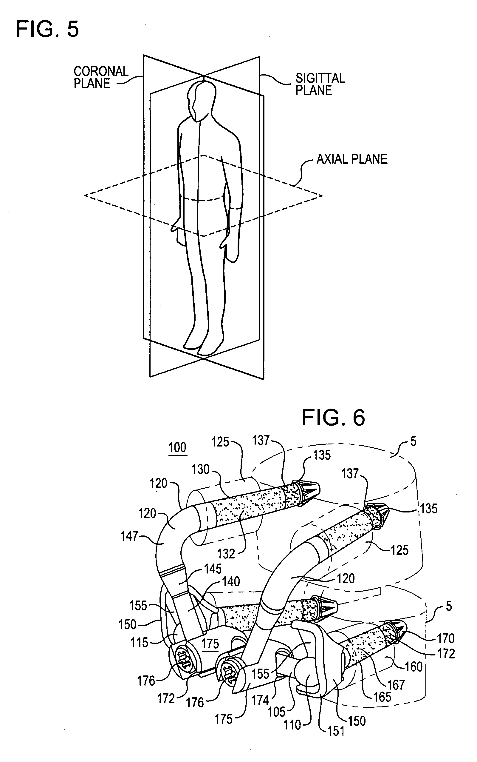
[0074] The crossbar 105, in a first embodiment, has a first end 110 and a second end 115. In the illustrated embodiment the crossbar 105 is a two piece bar where the first end 110 is attached to a threaded male portion 104 having threads 109. The crossbar second end 115 is attached to a threaded female portion 106 sized to receive the threads 109. As will be described in greater detail below, the threaded ends allow for the width of the crossbar to be adjusted to mate with the width between caudal bearings 150 (FIG. 9). Additional alternative embodiments of the crossbar 105 could include a series of solid crossbars of varying widths and / or thicknesses, or an adjustable crossbar having some form of locking or biasing mechanism (such as a spring-loaded tensioner or detent mechanism, etc.).

[0075] A pair of cephalad prosthesis elements 120 are also illustrated in the exemplary embodiment of the configurable and adaptable spinal prosthesis 100 of the present invention. Each cephalad pros...

embodiment 330

[0167]FIG. 31C illustrates an embodiment of an adaptive spinal prosthesis 300C having a crossbar embodiment 330 and crossbar locks 331. A crossbar lock 331 includes a cephalad arm clamp 334 about a cephalad arm 145 and a crossbar clamp 336 that encircles the crossbar 330. A dual clamp housing 332 and fastener 338 join the clamps 334, 336. The width of crossbar 330 is determined by moving the crossbar 330 relative to the crossbar clamps 336. The crossbar spacing between a cephalad bearing 305 and an elbow 147 is determined by moving the cephalad arm clamp 334 along the cephalad arm 147 to the desired position. Once the width of crossbar 330 and the position of the crossbar 330 relative to the bearing 305 and the elbow 147 are selected, the crossbar 330 is secured into the selected position by tightening the fastener 338. Tightening fastener 338 results in articulation within dual clamp housing 332 to tighten both the arm clamp 334 about the cephalad arm 145 and the crossbar clamp 336...

embodiment 340

[0168]FIG. 31D illustrates an embodiment of an adaptive spinal prosthesis 300D having a crossbar embodiment 340 with crossbar locks 341. A crossbar lock 341 includes a cephalad arm clamp 342, a crossbar clamp 344 and a fastener 346. The position of the crossbar 340 between the cephalad bearing 305 and the elbow 147 is changed by sliding the arm clamps 342 along the cephalad arms 147. The crossbar width between the crossbar clamps 344 is adjusted by sliding the crossbar 344 relative to the clamps 344. Once the position of the crossbar 340 between the cephalad bearing 305 and the elbow 147 and the width of the crossbar 340 are selected, the crossbar position is secured by tightening fastener 346. Tightening fastener 346 urges the arm clamp 342 about the cephalad arm 145 and the crossbar clamp 344 about the crossbar 340. In the illustrated embodiment, the crossbar 340 is contained in a plane above a plane that contains the cephalad arms 145, though it could be even with or below the pl...


PUM


Abstract

Modular spinal prosthesis having one of both of adaptable and configurable components are provided. The modular spinal prosthesis described herein provide an artificial articular configuration to replace damaged, worn or otherwise removed spinal facet elements.

Description

CROSS-REFERENCE [0001] This application is a continuation in part of commonly assigned U.S. Non-Provisional patent application Ser. No. 10 / 831,657 to Tokish et al., filed Apr. 22, 2004, and entitled “Anti-Rotation Fixation Element for Spinal Prosthesis,” which is incorporated herein by reference.FIELD OF THE INVENTION [0002] The present invention generally relates to devices and surgical methods for the treatment of various types of spinal pathologies. More specifically, the present invention is directed to several different types of highly configurable and anatomically adaptable spinal joint replacement prostheses and surgical procedures for performing spinal joint replacements. BACKGROUND OF THE INVENTION [0003] The human spinal column 10, as shown in FIG. 1, is comprised of a series of thirty-three stacked vertebrae 12 divided into five regions. The cervical region includes seven vertebrae, known as C1-C7. The thoracic region includes twelve vertebrae, known as T1-T12. The lumbar...

Claims


Application Information

Patent Timeline
IPC IPC(8): A61B17/17A61F2/00A61F2/30A61F2/44A61F2/46
CPCA61B17/15A61F2/44A61B17/7064A61F2/30742A61F2/4405A61F2/442A61F2/4455A61F2002/30092A61F2002/30171A61F2002/30289A61F2002/30331A61F2002/30405A61F2002/30462A61F2002/30507A61F2002/30537A61F2002/30538A61F2002/3055A61F2002/30563A61F2002/30566A61F2002/30579A61F2002/30601A61F2002/30604A61F2002/30607A61F2002/30616A61F2002/30617A61F2002/30682A61F2002/3069A61F2002/3082A61F2002/30841A61F2002/30845A61F2002/30846A61F2002/3085A61F2002/30878A61F2002/30881A61F2002/30884A61F2002/448A61F2002/4631A61F2210/0014A61F2220/0025A61F2220/0033A61F2220/0075A61F2230/005A61F2230/0091A61F2250/0004A61F2250/0006A61F2250/0007A61F2250/0062A61F2250/0097A61F2310/00023A61B17/7049A61B2017/564
Inventor KUIPER, MARK K.YAGER, DAVIDTOKISH, LEONARD JR.ROSLER, DAVID MICHAELROGERS, SUSAN L.RALPH, CHRISTOPHERCHARBONNEAU, MARKBROMAN, RICHARDSTINSON, DAVIDREILEY, MARK A.
Owner FACET SOLUTIONS
Why Eureka
Try Eureka