
Surgery delivery device and mesh anchor

Active Publication Date: 2005-10-27
TYCO HEALTHCARE GRP LP
View PDF35 Cites 687 Cited by
  • Summary
  • Abstract
  • Description
  • Claims
  • Application Information

AI Technical Summary

Benefits of technology

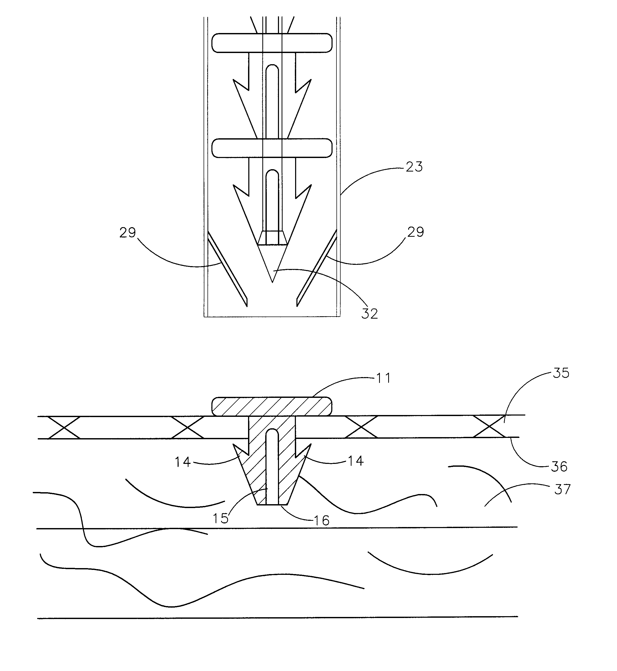
[0012] A delivery device for delivering a plurality of individual surgical anchors is disclosed. The delivery device comprises a housing, a delivery tube, having a distal and a proximal end, an actuator, flexible anchor reaction members, a reciprocating anchor carrier, having a distal and a proximal end and a distal and proximal position, the distal end terminating in a tissue penetrator. The device further includes at least one surgical anchor located in juxtaposition with the anchor carrier and a queuing spring to urge the anchors distally. Each of the surgical anchors has a penetration section and a head section. The surgical anchors are preferably made from an absorbable polymer. The actuator is connected to the anchor carrier and has at least two states. The first, or home state, comprises a position such that the surgical anchor is proximal the distal end of the delivery tube. The second state is such that the penetrating section of the surgical anchor is exposed beyond the distal end of the delivery tube. The anchor of the present invention is then deployed by simply applying a distal force to the handle of the housing and penetrating the prosthesis and tissue. A reaction member formed inside and affixed to the delivery tube provides a stop against which the reaction force of penetration is applied to the head section of the anchor. When the surgeon is ready to deploy the anchor a trigger, part of the actuator, is held stationary against the handle such that no dynamic countervailing forces are encountered. The anchor has a centered internal channel through which the cylindrical anchor carrier passes. The distal penetrating tip of the anchor c

Problems solved by technology

The head of the anchor engages the prosthesis and thus provides a stop that does not allow the anchor to traverse the prosthesis as sometimes happens in the use of the helical fastener.

Method used


Image

  • Surgery delivery device and mesh anchor
  • Surgery delivery device and mesh anchor
  • Surgery delivery device and mesh anchor

Examples


Embodiment Construction

[0025] The present invention relates to a surgical device and, more particularly, to a surgical device for serially deploying at least one surgical anchor from a surgical device to attach a prosthesis in place in the repair of a defect in tissue such as an inguinal hernia.

[0026] The present invention is illustrated and described in conjunction with a repair of an inguinal hernia, by way of example, however, it should be understood that the present invention is applicable to various other surgical procedures that require the repair of defects in tissue.

[0027] The Anchor

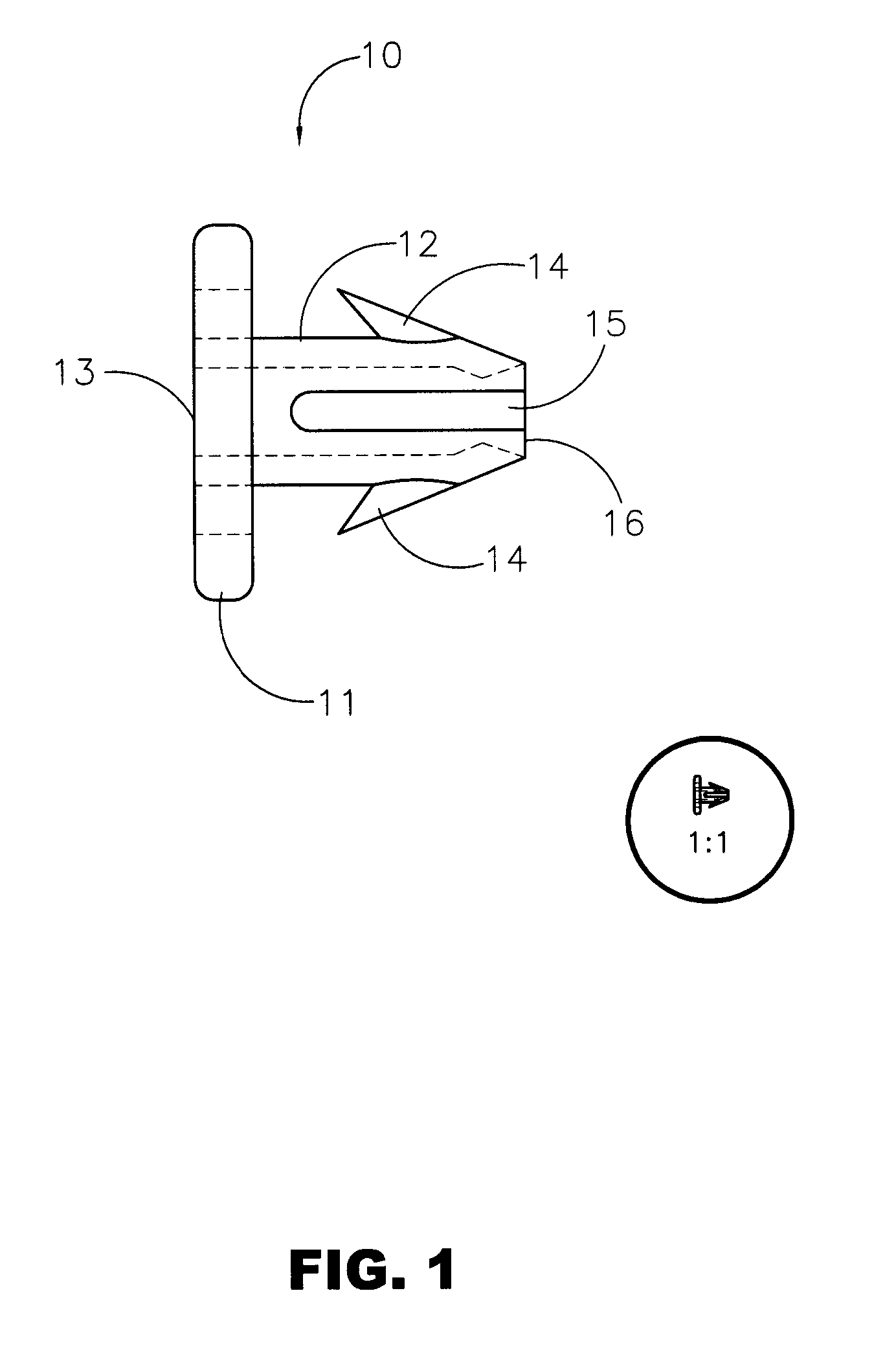
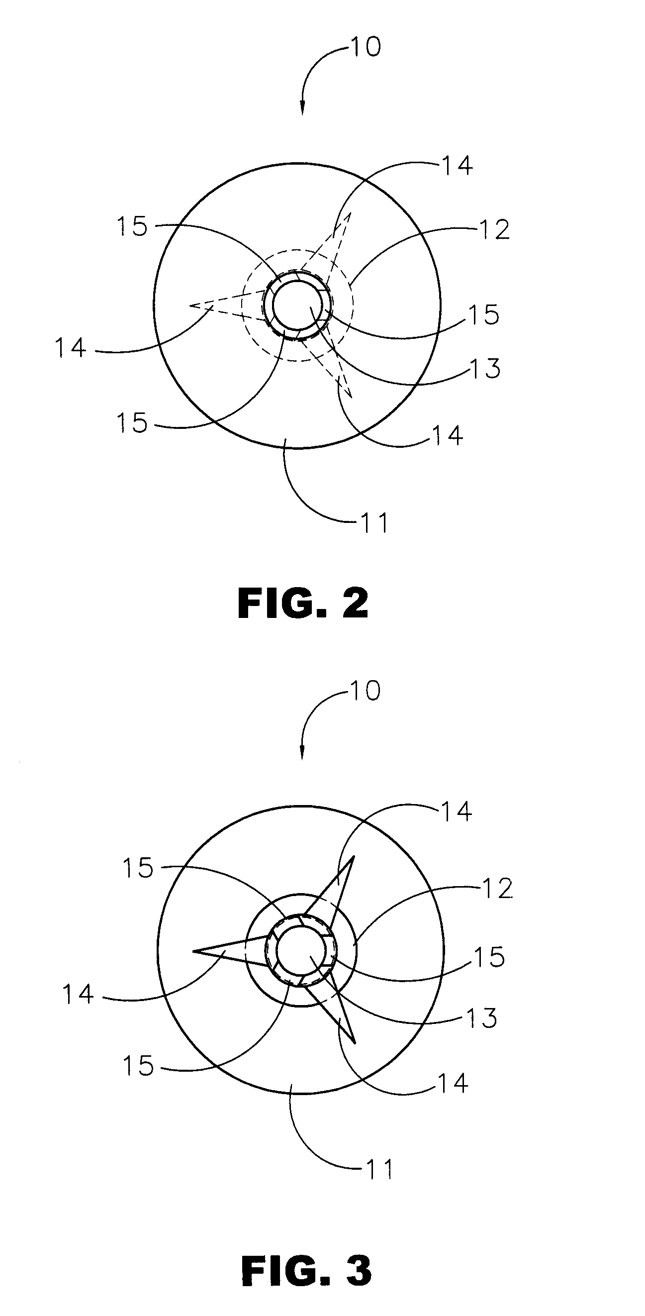
[0028] Referring to FIGS. 1, 2, and 3, the anchor of the present invention is generally designated by the number 10. Anchor 10 comprises a penetration shaft section 12, a head 11, and three rigid barbs 14. Internal channel 13 is concentric with the longitudinal axis and three slits 15 are equally spaced around penetration shaft 12. The distal end of anchor 10 is designated 16. Penetration shaft 12 is tapered from th...


PUM


Abstract

A delivery device for delivering a plurality of individual surgical anchors is disclosed. The delivery device comprises a housing, a delivery tube, having a distal and a proximal end, an actuator, flexible anchor reaction members, a reciprocating anchor carrier, having a distal and a proximal end, the distal end terminating in a tissue penetrator. The device further includes at least one surgical anchor located in juxtaposition with the anchor carrier. Each of the surgical anchors has a penetration section and a head section. The surgical anchors are preferably made from an absorbable polymer. The actuator is connected to the anchor carrier and has at least two states. The first, or home state, comprises a position such that the surgical anchor is proximal the distal end of the tube. The second state is such that the penetrating section of the surgical anchor is exposed beyond the distal end of the delivery tube.

Description

BACKGROUND OF INVENTION [0001] An inguinal hernia is formed when small a loop of bowel or intestine protrudes through a weak place or defect within the lower abdominal muscle wall or groin. This condition is rather common, particularly in males. Hernias of this type can be a congenital defect or can be caused by straining or lifting heavy objects. The protrusion results in an unsightly bulge in the groin area often causing pain, reduced lifting ability, and in some cases, impaction of the bowel. [0002] Surgery is a common solution to this problem. The preferred surgical technique requires extracting the bowel from the defect, placing a surgical prosthesis such as a mesh patch over the open defect, and attaching the mesh patch to the inguinal floor with conventional sutures or with surgical fasteners or anchors. The repair is accomplished using either open or laparoscopic surgery. Surgical anchors are routinely used in the laparoscopic procedures owing to the difficulty in suturing u...

Claims


Application Information

Patent Timeline
IPC IPC(8): A61B17/00A61B17/064A61B17/068A61B17/08
CPCA61B17/00234A61B17/064A61B2017/0647A61B2017/00004A61B17/068
Inventor SHIPP, JOHN I.
Owner TYCO HEALTHCARE GRP LP
Learn More