Retaining clip for reagent test slides
a technology for reagent test slides and clips, which is applied in the field of holding and storage devices to achieve the effect of reducing the contamination of slides
- Summary
- Abstract
- Description
- Claims
- Application Information
AI Technical Summary
Benefits of technology
Problems solved by technology
Method used
Image
Examples
first embodiment
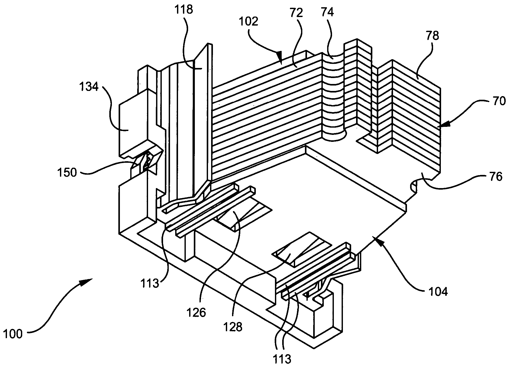
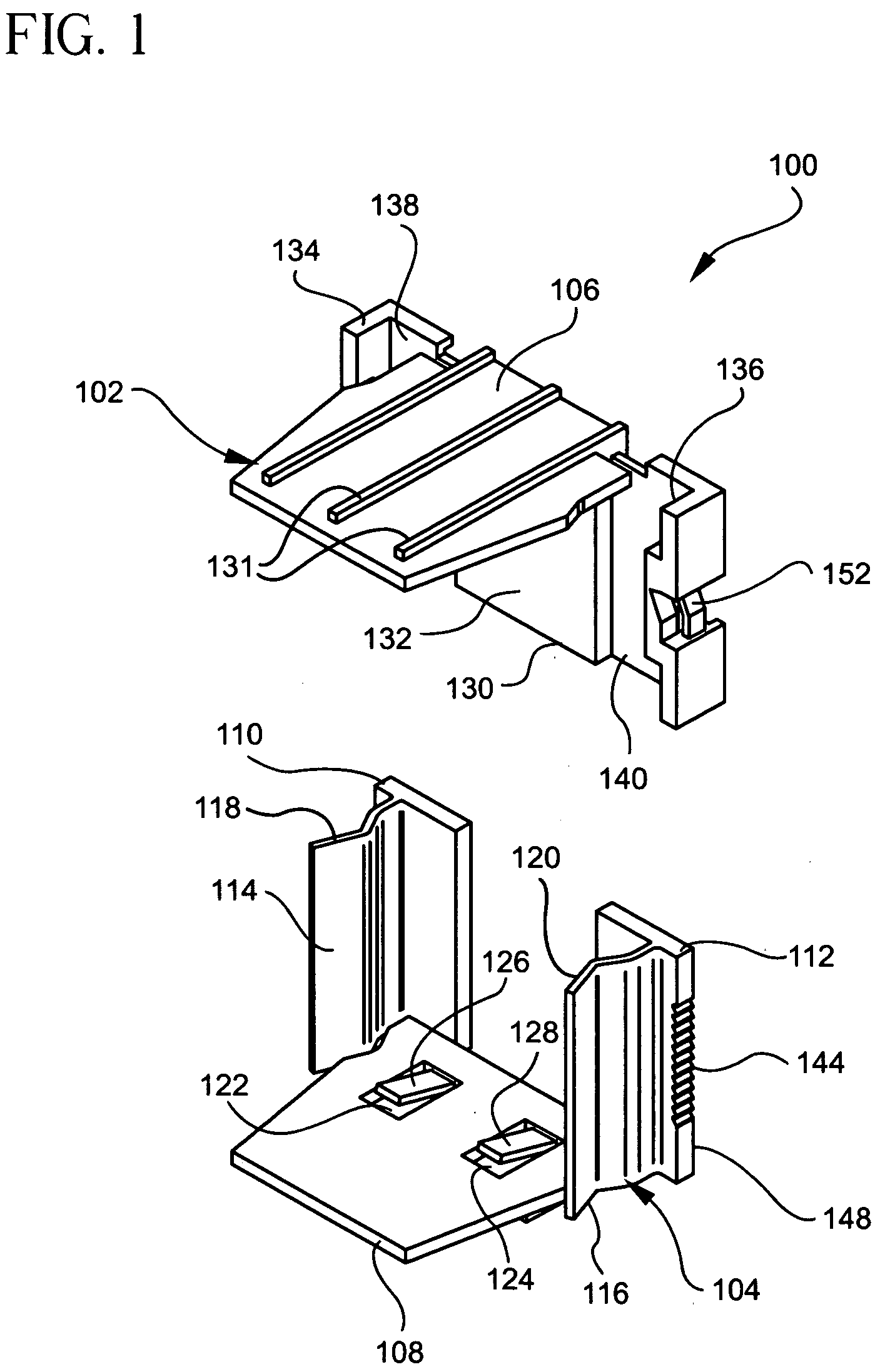
[0068] a retaining clip 100 formed in accordance with the present invention is illustrated by FIGS. 1-16 of the drawings. The retaining clip 100 of this particular embodiment includes a top cover assembly 102 and a bottom cover assembly 104. The top cover assembly 102 includes a top cover plate 106, and the bottom cover assembly 104 includes a bottom cover plate 108. The top cover plate 106 and the bottom cover plate 108 define between them a space for receiving a plurality of reagent test slides.
[0069] The bottom cover assembly 104 includes the bottom cover plate 108, as mentioned previously, and a first rail 110 and a second rail 112 extending parallelly in the same direction from, and affixed to, the bottom cover plate 108. Each of the first and second rails 110 and 112 are plate-like in formation, and includes free standing, resilient members 114 and 116 biased inwardly toward one another into the space for receiving the reagent test slides 70 (see FIG. 14). As will be seen, eac...
second embodiment
[0080] The retaining clip 200 of the second embodiment further includes a top cover plate 212 which is slidably mounted on the back wall 204. More specifically, the top cover plate 212 includes a generally planar main body portion 214, and a T-shaped extension 216 which extends from its rear edge 218 of the main body portion 214. The T-shaped extension 216 includes a narrow portion 227 extending outwardly from the main body portion 214, and a widened portion 226 joined to the end of the narrow portion 227. This T-shaped extension 216 is slidingly received by a slot 225 formed preferably centrally through the thickness of the back wall 204 and extends at least partially longitudinally along the back wall 204 between the bottom cover plate 202 and the top edge 203 of the back wall 204. The slot 225 in the back wall 204 is particularly dimensioned to have a width W3 which is equal to or slightly greater than the width W4 of the narrower portion 227 of the T-shaped extension 216 of the ...
third embodiment
[0094] As in the previous embodiment illustrated by FIGS. 17-22, the third embodiment illustrated by FIGS. 23-28 includes a handle 354 for grasping by the user. The handle 354 extends outwardly and preferably perpendicularly from the rear surface 355 of the back wall 304 and is connected to the rear surface 355 through a bi-directional living hinge 356. Unlike the previous embodiment illustrated by FIGS. 17-20, in this particular embodiment, the bi-directional living hinge 356 is used to mount the handle 354 to the back wall 304 and to allow the handle 354 to be moved from its outwardly extended position to a folded, unextended position against or in close proximity to the rear surface 355 of the back wall 304 in the direction of either one lateral side wall 306 or the other lateral side wall 308.
[0095] Preferably, the handle 354 is T-shaped in longitudinal cross-section, and is formed with an extended portion 358 which is joined to the living hinge 356, and a transverse section 360...
PUM
| Property | Measurement | Unit |
|---|---|---|
| angle | aaaaa | aaaaa |
| thickness | aaaaa | aaaaa |
| resilient | aaaaa | aaaaa |
Abstract
Description
Claims
Application Information
 - R&D
- Intellectual Property
- Life Sciences
- Materials
- Tech Scout
- Unparalleled Data Quality
- Higher Quality Content
- 60% Fewer Hallucinations
Browse by: Latest US Patents, China's latest patents, Technical Efficacy Thesaurus, Application Domain, Technology Topic, Popular Technical Reports.
© 2025 PatSnap. All rights reserved.Legal|Privacy policy|Modern Slavery Act Transparency Statement|Sitemap|About US| Contact US: help@patsnap.com


