Method and device to enhance the readability of a liquid crystal display through polarized lenses

Inactive Publication Date: 2005-10-27
VISION EASE LENS +1
View PDF5 Cites 195 Cited by
  • Summary
  • Abstract
  • Description
  • Claims
  • Application Information

AI Technical Summary

Benefits of technology

[0008] In order to address the aforementioned need, the present invention pertains to a method of enhancing the readability of an LCD when viewed through a pair of polarized sunglasses, by placing an optical film at a certain orientation to disturb the polarized light out of the LCD. This invention also relates to a polarizing plate comprising such an optical film on one side of the polarizing film with a certain orientation. This invention further relates to an LCD setup that has such an optical film on top with a certain orientation, or an LCD setup that uses the inventive polarizing plate as the top polarizer covered with the optical film facing of the present invention. The method of this invention can be advantageously used to improve the readability of LCDs such as those in automobile dash displays, cellular phones, and flat panel screens, and avoid total blackout of the display when viewed through polarized lenses.
[0009] Thus, it is the object of this invention to provide a method to enhance the readability (view-ability) of an LCD that has a front polarizer when the LCD is viewed through polarized lenses.

Problems solved by technology

Ironically, these uses can conflict with each other.
Because the light passing through an LCD has been filtered by a polarized substrate, it is vulnerable to being completely blocked by a pair of polarized sunglasses.
In other words, if a person is wearing a pair of polarized sunglasses, they may be unable to see an LCD.
Because LCDs are used in a wide variety of applications, e.g. cellular telephones, calculators, watches, televisions, computers, etc., the chance of interference while wearing polarized sunglasses is significant.
If the polarization axis of the outermost polarizing plate of the LCD is horizontal, a driver would be unable to see the display while wearing vertically polarized sunglasses.
This problem could be potentially dangerous if the operator of a vehicle misses an important indication on the LCD.
However, unless the polarization axes of both the sunglasses and the LCD are parallel, there will be a degree of degradation.
Additionally, with an LCD polarization angle of between zero and ninety degrees, complete blockage by a sunglass user with his or her head tilted becomes more likely.

Method used


Image

  • Method and device to enhance the readability of a liquid crystal display through polarized lenses
  • Method and device to enhance the readability of a liquid crystal display through polarized lenses
  • Method and device to enhance the readability of a liquid crystal display through polarized lenses

Examples


example

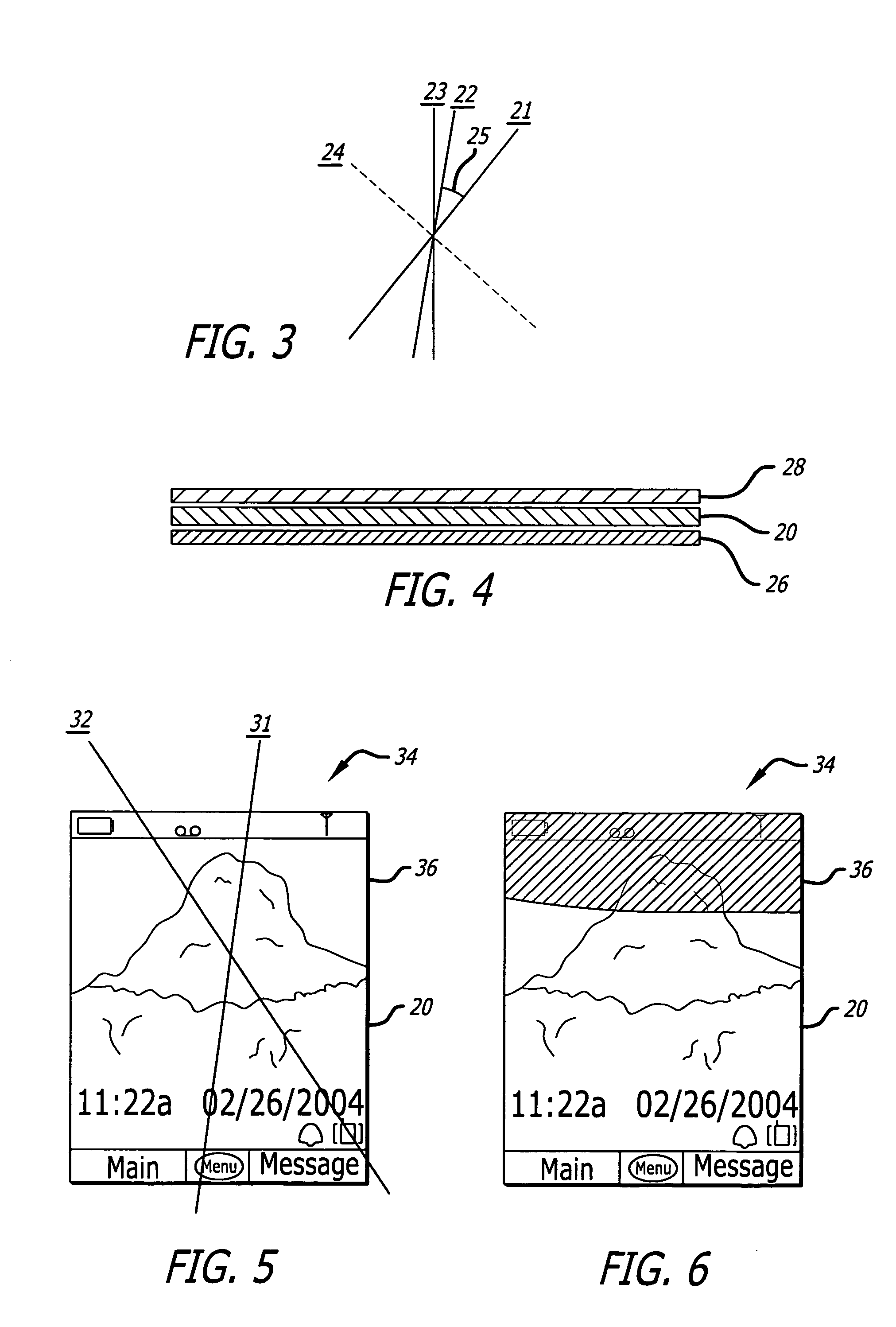
[0034] Referring to FIGS. 5 and 6, a retardation film 20 of the present invention has been constructed of polycarbonate and has a retardation value of 135 nm. The retardation film 20 was placed on a bottom portion of the LCD display 34 of a cellular telephone. The polarized light out of the LCD 34 has a polarization direction 31 about 150 off the vertical direction. The optical axis 32 of the retardation film 20 forms a 45° angle with the LCD's polarized light. FIG. 5 shows that the film 20 is virtually invisible to the naked eye, as compared to the area 36 on the LCD 34 that is not covered by the film 20. FIG. 6 shows the film as viewed through polarized glasses. It is readily apparent that the retardation film 20 eliminates the possibility of blackout of the display in the regions where the retardation film is affixed to the LCD when viewed through a pair of polarized sunglasses, regardless of the polarizing direction of the polarized lenses.


PUM


Abstract

An optical film is placed over a liquid crystal display to manipulate the polarized light exiting the top polarizing layer of the display such that the light is less likely to become blocked out by the polarized sunglasses of a user viewing the device. The manipulation may include retarding the axis of the light or diffusing the light.

Description

RELATED APPLICATIONS [0001] This application claims priority to U.S. Provisional Application Ser. No. 60 / 553,649, entitled Method To Enhance The Readability of LCD Display Through Polarized Lenses, filed on Mar. 16, 2004, and incorporated in its entirety herein.BACKGROUND [0002] Polarizing is a process by which extremely tiny parallel lines of dye are created on a transparent substrate, such as a lens, crystal or sheet. These tiny lines block light rays that are not aligned with the lines. Light rays travel in a sinusoidal pattern. The oscillations are planar but each ray may oscillate in a different plane. Thus, polarized substrates block all rays that are not oscillating in a plane that is substantially parallel to the direction of the polarized lines. [0003] Polarized substrates have a variety of uses. For example, polarized sunglasses are popular because they filter glare from horizontal surfaces such as roads and lakes. Reflected light tends to oscillate in planes that coincide...

Claims


Application Information

Patent Timeline
IPC IPC(8): G02F1/1335G02F1/13363
CPCG02F1/133504G02F1/13363G02F2413/05G02F2001/133638G02F2413/04G02F2001/133562G02F1/133562G02F1/133638
Inventor SUGIMURA, HIDEYOQIN, XUZHI
Owner VISION EASE LENS
Why Eureka
Try Eureka