
Image display device

Inactive Publication Date: 2005-10-27
SCALAR CORP
View PDF5 Cites 52 Cited by
  • Summary
  • Abstract
  • Description
  • Claims
  • Application Information

AI Technical Summary

Benefits of technology

[0013] The present invention is an image display device comprising a main body that can be worn on the head of a user; right-eye display means for displaying a predetermined image, said right-eye display means being provided on or in said main body in such a manner that said image is blurred or beyond the visible range of the right eye of said user when said user wearing said main body on his or her head looks straight ahead, and that said image is caught by the right eye of said user when said user moves his or her straight-looking right eye away; and left-eye display means for displaying a predetermined image, said left-eye display means being provided on or in said main body in such a manner that said image is blurred or beyond the visible range of the left eye of said user when said user wearing said main body on his or her head looks straight ahead, and that said image is caught by the left eye of said user when said user moves his or her straight-looking left eye away. In this image display device, good visibility is obtained for both eyes when said user wearing said main body on his or her head looks straight ahead. In addition, said right-eye display means and / or said left-eye display means are / is provided in such a manner that they / it can be positioned and fixed to said main body at a certain position or positions suited for the right and left eyes of said user.
[0033] When each of said right-eye display means and said left-eye display means is formed as an integrated unit, said optical system contained in said right-eye display means and said left-eye display means may comprise lenses for focusing an image displayed on said display screen to the retina of the right or left eye of said user. The lenses in this case are designed in such a manner that the central axis of the lens for the right eye generally coincides with the line of sight of the right eye of said user and the central axis of the lens for the left eye generally coincides with the line of sight of the left eye of said user when said user moves his or her right or left eye down at said predetermined angle equal to or larger than 20 degrees. This provides easier viewing of images displayed on said right-eye display means and said left-eye display means when said user moves his or her eyes down at a predetermined angle equal to or larger than 20 degrees and they become clearly visible for said user, suppressing eyestrain.

Problems solved by technology

Seeing images with one eye often triggers user eyestrain and places a heavy burden on the beholding user.
Therefore, this image display device is not suited for use for prolonged periods of time.
Even with an image display device having two display means, a mismatch between the user and the two display means can cause eyestrain of the user.
There has been no image display device of the type that presents images in a certain part of the field of vision in which the image display device solves the aforementioned problems and gives a user the opportunity of its use for prolonged periods of time, sometimes of a long-time viewing of images.

Method used


Image

  • Image display device
  • Image display device
  • Image display device

Examples


first embodiment

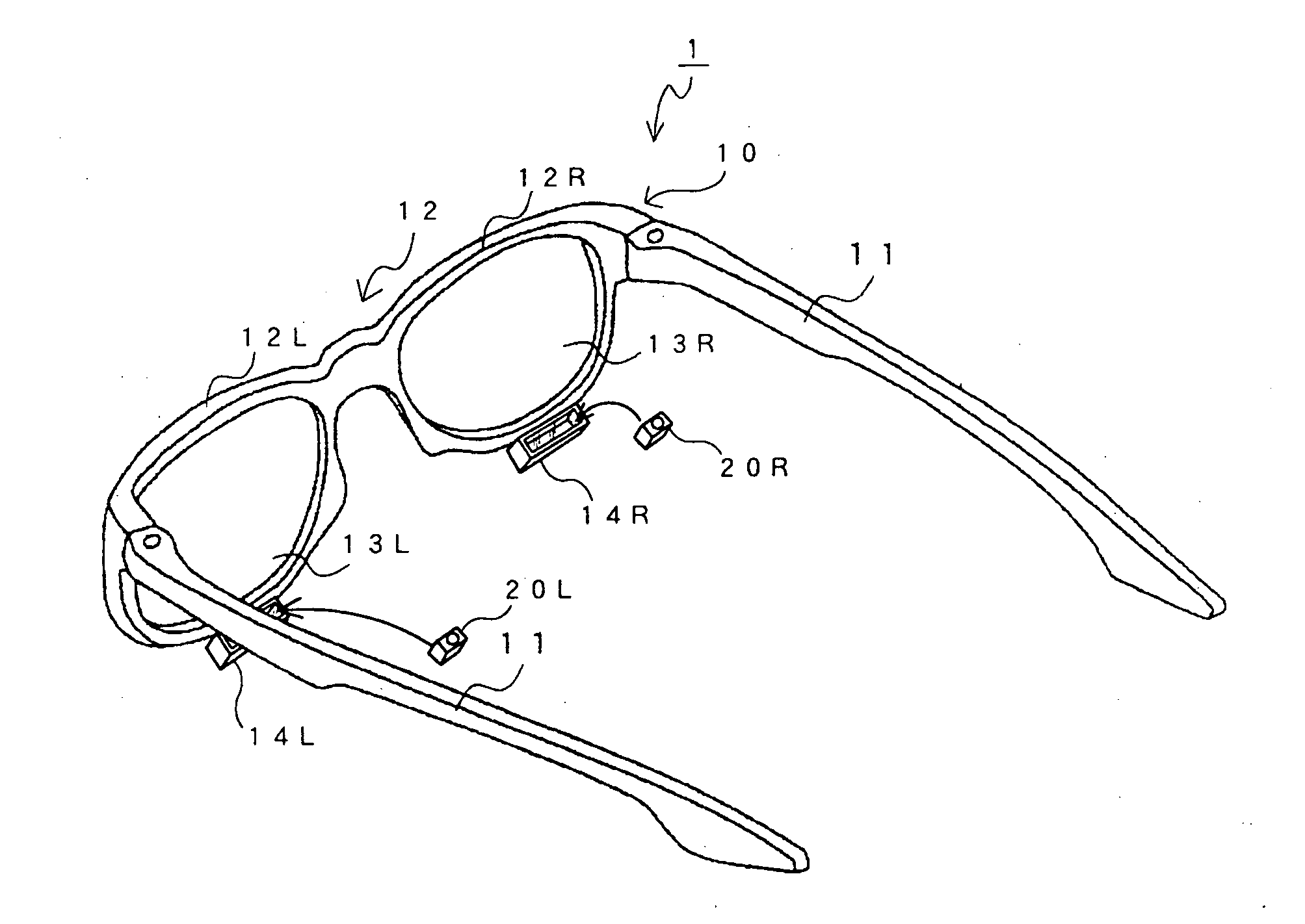
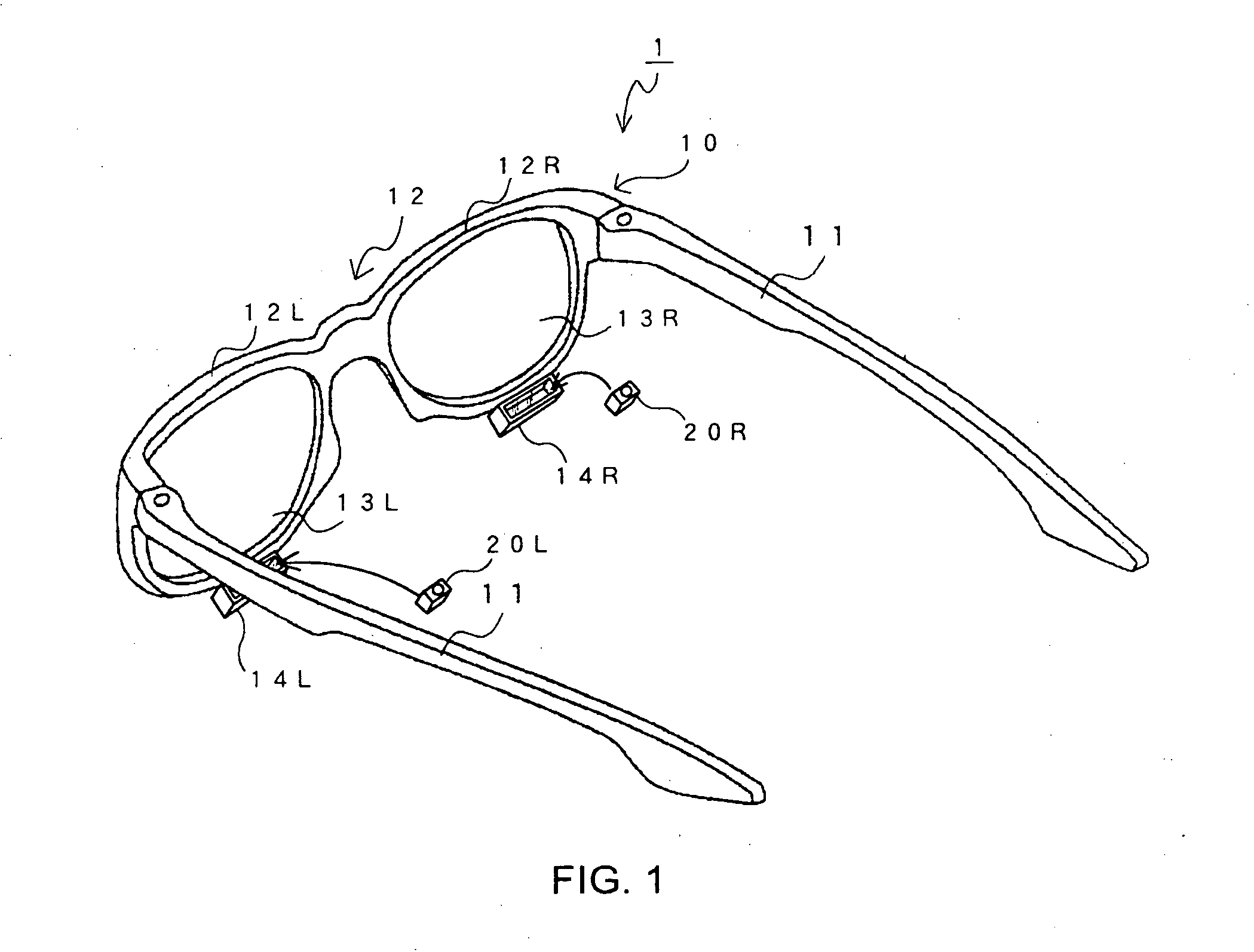
[0047]FIG. 1 is a perspective view showing the whole of an image display device 1, seen from the back, according to a first embodiment of the present invention.

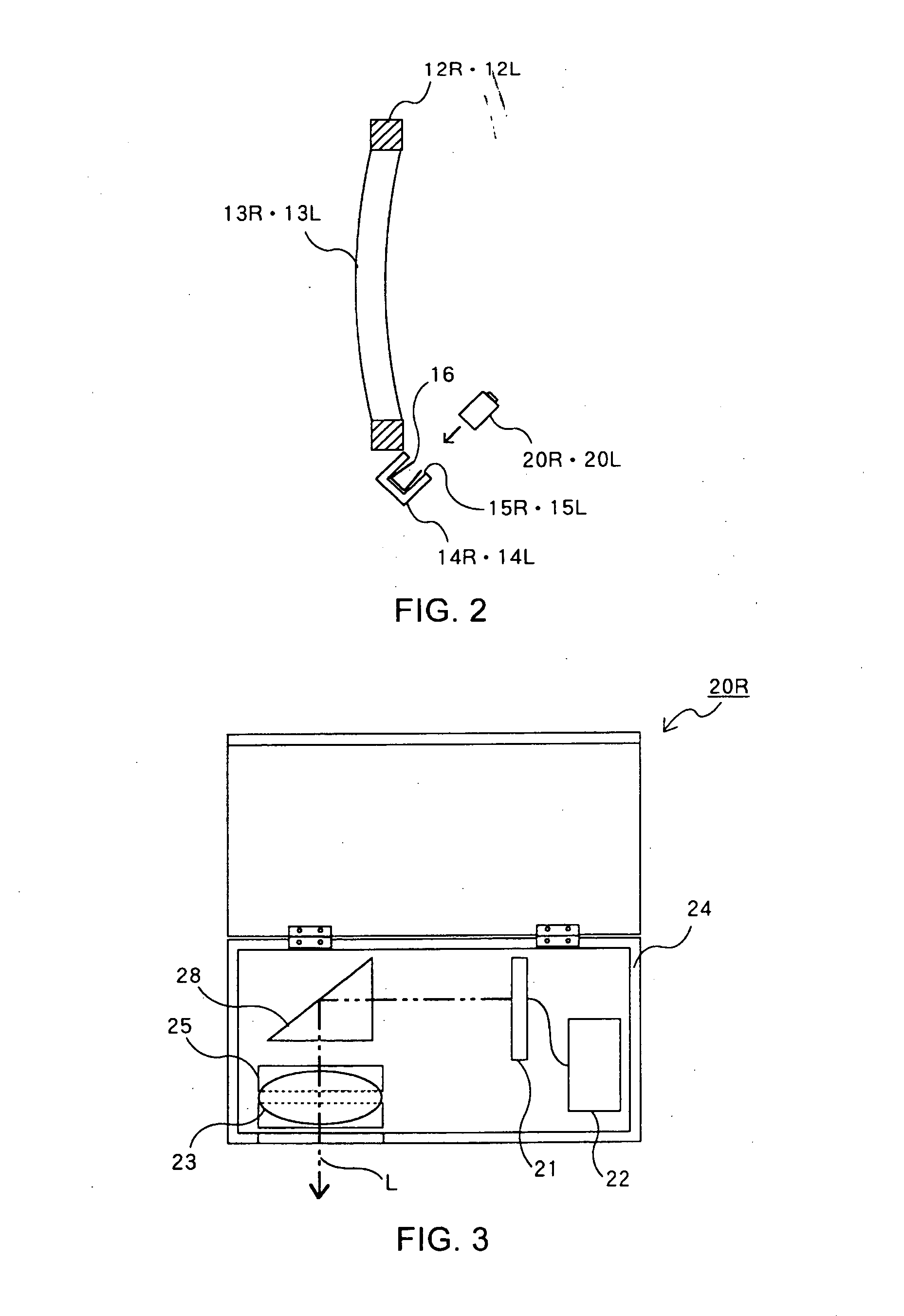
[0048] This image display device 1 comprises a main body 10, and a right-eye display device 20R and a left-eye display device 20L for displaying images.

[0049] The main body 10 in this embodiment has a shape of, but not limited to, a glasses frame. It comprises temples 11 and a frame 12.

[0050] The image display device 1 is used while worn on the head of a user. The temples 11 fit over the user's ears to keep the image display device 1 on the head of the user.

[0051] The frame 12 includes a right-eye frame 12R and a left-eye frame 12L. The right-eye frame 12R is a frame segment that rests in front of the right eye of the user when the image display device 1 is kept on the head of the user. The left-eye frame 12L is a frame segment that rests in front of the left eye of the user when the image display device 1 is mounted. Whi...

second embodiment

[0085]FIG. 7 is a perspective view showing the whole of an image display device 2, seen from the front, according to a second embodiment of the present invention.

[0086] The image display device 2 comprises a main body 10, and a right-eye display device 20R and a left-eye display device 20L for displaying images as in the image display device 1 of the first embodiment.

[0087] The image display device 2 has a structure similar to that of the image display device 1 of the first embodiment. A way of using it is also similar. In particular, details of the right-eye display device 20R and the left-eye display device 20L are completely same as those in the image display device 1 of the first embodiment.

[0088] The difference between the image display device 2 of the second embodiment and the image display device 1 of the first embodiment lies in the structure of their main bodies 10 and the mechanism that is used to attach the right-eye socket 14R and the left-eye socket 14L to the main b...


PUM


Abstract

To provide an image display device of the type that presents images in a certain part of the field of vision in which the image display device can be used for prolonged periods of time. An image display device 1 includes a main body 10 having a shape of a glasses frame, a right-eye display device 20R and a left-eye display device 20L. Each of the right-eye display device 20R and the left-eye display device 20L is for displaying a predetermined image and is provided in such a manner that it is not very clearly visible for a user when the user wearing the main body 10 on his or her head looks straight ahead and that it becomes clearly visible for the user only when the user moves his or her forward-looking eyes away. The user can get a forward field of vision and can see the images displayed on the right-eye display device 20R and the left-eye display device 20L when he or she looks at 45 degrees down. The right-eye display device 20R and the left-eye display device 20L may be fixed to the main body 10 at a spacing corresponding to the distance between the eyes of the user.

Description

TECHNICAL FIELD [0001] The present invention relates to a small image display device that can be used while worn on the head. BACKGROUND OF THE INVENTION [0002] Head mounted displays (HMDs), which are used while worn on the head to place a video screen in front of each eye of the user, find applications in various fields including the field of virtual reality. Typical HMDs are designed in the shape of a frame of goggles or large glasses that block out outside light and force the user to see only the HMD's pictures. With an HMD used, the user can view images irrespective of the direction he or she faces but then again it gives the user visual isolation from the surrounding environment. [0003] In recent years, small image display devices have been proposed that allow users to view both images and the surrounding environment by means of presenting the images in a certain part of the field of vision. [0004] The image display device of this type is disclosed in, for example, Japanese pat...

Claims


Application Information

Patent Timeline
IPC IPC(8): G02B7/12G02B27/00G02B27/01G02C11/00
CPCG02B7/12G02B27/017G02B27/0172G02C11/00G02B2027/0132G02B2027/0178G02B27/0176G02B27/02
Inventor YAMAMOTO, MASAO
Owner SCALAR CORP
Learn More