
Roll-formed panels for vehicle box assembly

a box assembly and roll-formed technology, applied in the direction of superstructure subunits, loading-carrying vehicle superstructures, monocoque constructions, etc., can solve the problems of unsatisfactory structural and economic factors, unsatisfactory surface stretch marks or blemishes, and formed members having greater weight than desired

Inactive Publication Date: 2005-10-27
PULLMAN IND
View PDF20 Cites 40 Cited by
  • Summary
  • Abstract
  • Description
  • Claims
  • Application Information

AI Technical Summary

Problems solved by technology

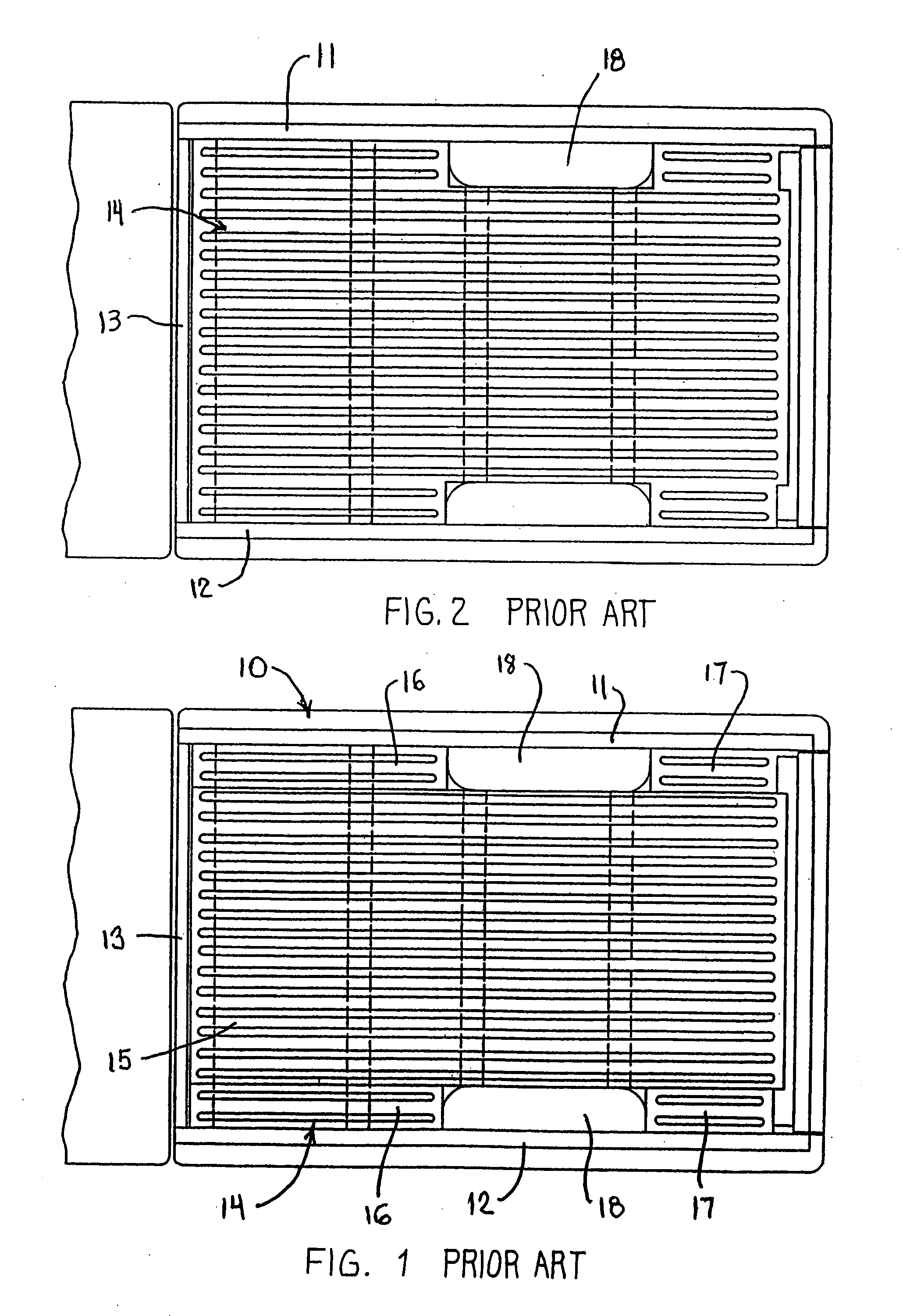
Forming the box predominantly from stamped sheet steel panels, however, results in structural and economic factors which are less than desirable.
A principal disadvantage associated with using stamped sheet steel panels is the fact that such panels require use of a greater quantity of material than is optimally desired, and also ultimately results in the formed members having greater weight than desired, both of which are undesirable from the standpoint of the overall vehicle.
Stamping large sheets to define large three-dimensional panels, such as for a vehicle box assembly, also often results in undesired surface stretch marks or blemishes in the finished product.
The stamping operation also typically requires that the sheet be significantly oversized relative to the finished product so as to permit trimming of the sheet around the entire peripheral edge of the finished stamped member, and this hence results in significant waste.
A further and significantly disadvantageous factor associated with use of stamped sheet steel panels for vehicle box assemblies is the cost associated with the manufacture of the required stamping tools, and the significant number of such tools required to form the different stamped panels.
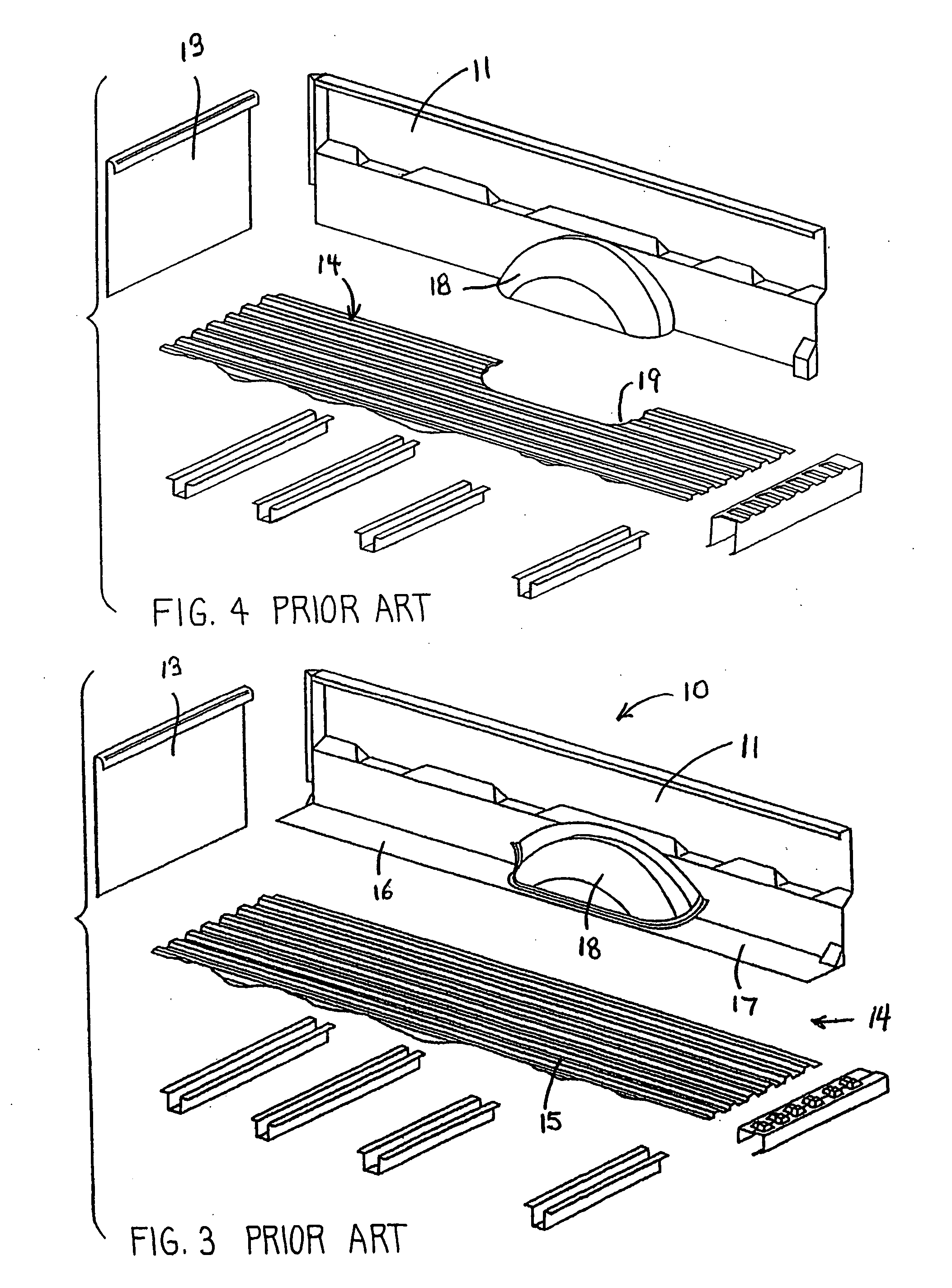
Since the stamped panels defining the front and side walls of the box assembly, as well as the bed, are all of rather large size, the stamping tool required to form a single panel is necessarily large and complex, and hence extremely costly to manufacture.
The complexity associated with such tooling is further increased by the fact that the side and front panels typically have reinforcing channels formed along the upper edges thereof, which channels define either inverted U-shaped configurations or sometimes even a closed hollow channel, whereby the stamping tooling for such shapes involves multiple stamping steps and hence is complex and expensive.
The cost of the stamping tooling is further exacerbated by the fact that each stamped part requires its own customized stamping tooling.
Needless to say, the overall net effect is that the tooling is not only extremely costly, but the tooling also requires significant floor space in the factory, and additional labor for operation thereof.
A box assembly having constructional features similar to that illustrated by FIG. 1 hence employs a large number of different stamped members, and accordingly requires large investment in tooling as well as significant factory space for production and assembly of such construction.
Such stamping, however, due to its size and complex three-dimensional shape, requires complex and costly tooling.

Method used


Image

  • Roll-formed panels for vehicle box assembly
  • Roll-formed panels for vehicle box assembly
  • Roll-formed panels for vehicle box assembly

Examples


first embodiment

[0051] Referring to FIGS. 5 and 6, there is illustrated an improved vehicle box assembly 21, specifically a box assembly for a pickup truck, according to the present invention.

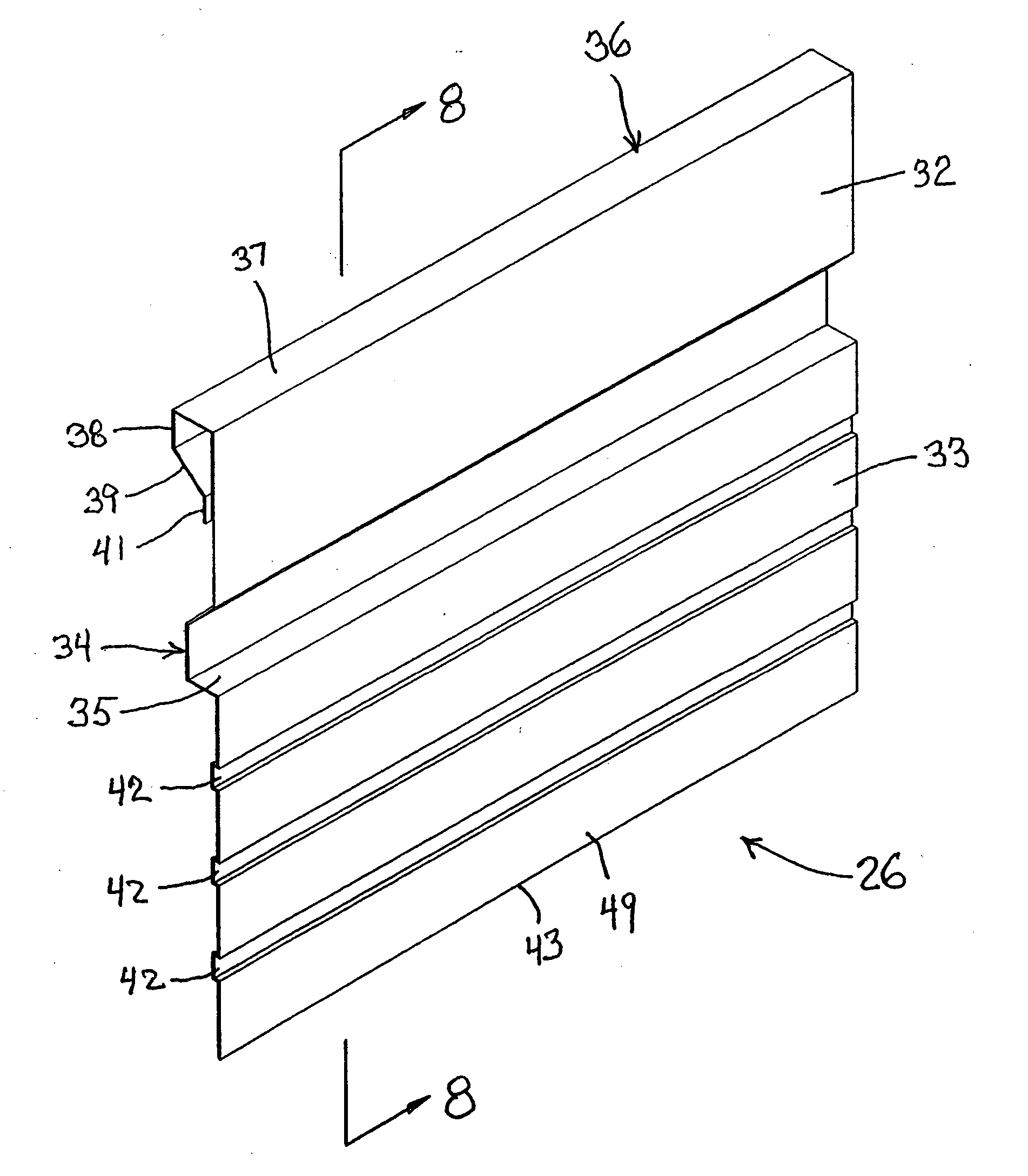
[0052] The box assembly 21 includes a bed or floor pan arrangement 22 which is supported on a plurality of support or cross rails extending transversely thereunder, including a front cross rail 23 disposed adjacent the forward end of the floor, one or more generally parallel intermediate cross rails 24 disposed in rearwardly spaced but generally parallel relationship beneath the floor, and a rear cross rail 25 which supportingly engages the floor beneath the rear edge thereof. An inner upright front panel 26 projects upwardly from the floor adjacent the front end of the box assembly, and opposed right and left inner upright side panels 27 project upwardly from opposite sides of the floor and have their forward edges rigidly joined to opposite ends of the front panel 26. Only the right side panel is illustrated...

second embodiment

[0089] Referring now to FIGS. 17-18, there is illustrated a box assembly 121, particularly for a pickup truck, according to the present invention.

[0090] The box assembly 121 again includes a floor or bed 122 supported on a plurality of underlying cross rails such as a front rail 123, plural intermediate rails 124 and a rear rail 125. An upright front panel 126 projects upwardly adjacent a front edge of the bed 122, and a side panel 127 projects upwardly adjacent each side of the bed, with a wheel well housing 128 cooperating between each side panel 127 and the respective side portion of the bed 122. The rear edge of the side panel cooperates with an upright or post 129.

[0091] In the box assembly 121, the bed 122 is defined by multiple bed sections, including a main center bed section 131 which extends lengthwise throughout the full length of the bed but has a width which is sized so as to extend generally only between the wheel wells, whereby the center bed section 131 has a genera...

third embodiment

[0100] the invention is illustrated by FIG. 22. The vehicle box assembly 161 illustrated in exploded view in FIG. 22, when assembled, will have the same appearance as shown by FIG. 18. The box 161 of FIG. 22 utilizes many of the same constructional features utilized in the box assembly of FIGS. 17-18, and hence corresponding parts thereof are identified by the same reference numerals and will not be separately discussed.

[0101] The principal difference between the box assembly 161 of FIG. 22 and the box assembly 121 of FIGS. 17-18 is the fact that the box assembly 121 (FIGS. 17-18) utilizes a one-piece press-formed inner quarter panel 135 for defining side panel 127, wheel well housing 128 and side bed section 131A. In contrast, the box assembly 161 of FIG. 22 utilizes a two-piece construction for defining these same functional members, namely a monolithic one-piece roll-formed panel member 162 which defines both the side panel 127′ and the side bed section 131A′ (herein referred to ...


PUM


Abstract

An improved vehicle box assembly with an upright front or side panel defined by a monolithic one-piece roll-formed steel sheet member having a desired three-dimensional configuration. The sheet steel member is roll-formed in the lengthwise direction thereof. The panel has a channel, preferably a closed tubular channel on the front panel, roll-formed along one edge of the sheet steel during forming of the panel. The closed tubular edge rail is preferably closed by a seam weld which extends lengthwise therealong and is performed in line with the roll-forming operation. The roll-formed panel is preferably provided with a flat shelf deformed horizontally to extend lengthwise along the panel downwardly from the top rail.

Description

CROSS-REFERENCE TO RELATED APPLICATIONS [0001] This application claims priority under 35 USC §119(e) of copending provisional application U.S. Ser. No. 60 / 561,803 filed Apr. 13, 2004, the entire disclosure of which is herein incorporated by reference.FIELD OF THE INVENTION [0002] This invention relates to a box assembly for a vehicle, such as a pickup truck, and more specifically to an improved construction of a vehicle box assembly employing roll-formed panels, and to the method of constructing the panels. BACKGROUND OF THE INVENTION [0003] The upwardly-opening box assembly associated with vehicles such as pickup trucks and the like have, for many years, employed a large plurality of stamped metal panels for defining the box. For example, in most instances the inner front and side panels of the box are stamped sheet steel members, and in most instances the bed of the box is also defined by one or more stamped sheetlike steel panels. Forming the box predominantly from stamped sheet ...

Claims


Application Information

Patent Timeline
IPC IPC(8): B62D25/16B62D33/02B62D33/023
CPCB62D33/023B62D25/16
Inventor MCNULTY, FRANK G.ZIMMERMAN, D. JAMESENGLER, EDWARD J.
Owner PULLMAN IND
Learn More