


Quick Research
Generate reliable direction feasibility study reports for your R&D in just a few steps.

Technical Q&A
Discover and master advanced knowledge NOW. Basics, ideas, possibilities, all at once.

Find Solutions
As an expert in R&D theories, this can generate solutions to your technical problems instantly.

Evaluate Feasibility
Analyze your overall solution with one click, know your potential R&D risks in advance.

Monitor Landscape
Get weekly tech updates, stay abreast of the latest tech innovations and key insights.
Self-propelled cleaner
a cleaner and self-propelled technology, applied in the direction of cleaning equipment, cleaning using liquids, applications, etc., can solve the problem that the technology cannot be used at places without rails
- Summary
- Abstract
- Description
- Claims
- Application Information
AI Technical Summary
Benefits of technology
Problems solved by technology
Method used
Image


Examples
Embodiment Construction
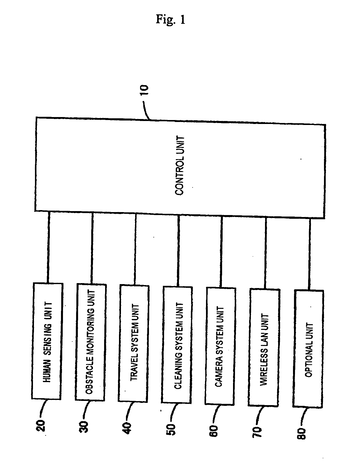
[0058]FIG. 1 is a block diagram showing the schematic construction of a self-propelled cleaning according to this invention. As shown in the figure, the cleaner comprises a control unit 10 to control individual units; a human sensing unit 20 to detect a human or humans around the cleaner; an obstacle detecting unit 30 to detect an obstacle or obstacles around the cleaner; a traveling system unit 40 for traveling; a cleaning system unit 50 to perform a cleaning; a camera system unit 60 to take an image of a predetermine range; a wireless LAN unit 70 for wireless connection to a LAN; and an optional unit 80 including additional sensors and the like. The body of the cleaner has a flat rough cylindrical shape.
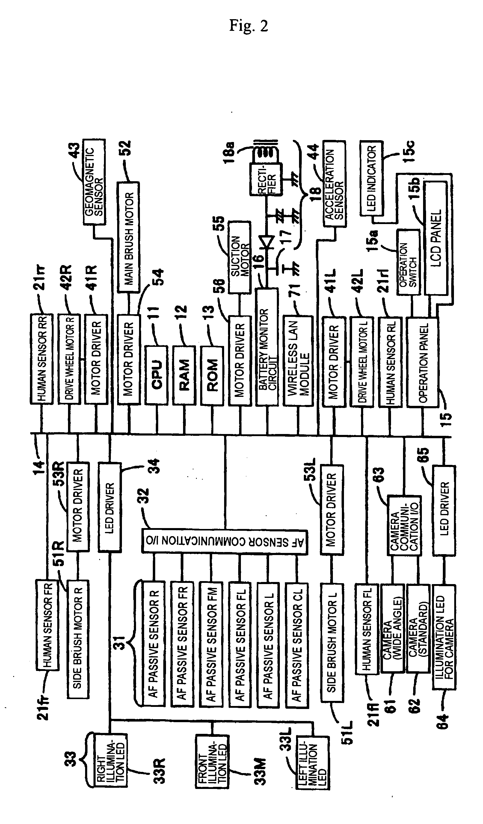
[0059]FIG. 2 is a block diagram showing the construction of an electric system that realizes the individual units concretely. A CPU 11, a ROM 13, and a RAM 12 are interconnected via a bus 14 to form the control unit 10. The CPU 11 performs various controls using the RAM 12 as a wo...
PUM
 Abstract
Description
Claims
Application Information
 - R&D Engineer
- R&D Manager
- IP Professional
- Industry Leading Data Capabilities
- Powerful AI technology
- Patent DNA Extraction
Browse by: Latest US Patents, China's latest patents, Technical Efficacy Thesaurus, Application Domain, Technology Topic, Popular Technical Reports.
© 2024 PatSnap. All rights reserved.Legal|Privacy policy|Modern Slavery Act Transparency Statement|Sitemap|About US| Contact US: help@patsnap.com