
Parallel decision-feedback decoder and method for joint equalizing and decoding of incoming data stream

Active Publication Date: 2005-10-20
REALTEK SEMICON CORP
View PDF7 Cites 3 Cited by
  • Summary
  • Abstract
  • Description
  • Claims
  • Application Information

AI Technical Summary

Benefits of technology

[0010] One objective of the claimed invention is therefore to provide a method for efficient and high-speed joint equalizing and decoding of an incoming data stream.

Problems solved by technology

Thus, demodulator / decoder architectures must be implemented with a degree of computational complexity that allows them to accommodate not only the “state width” of Trellis coded signals, but also the “dimensional depth” represented by the transmission channel.
A perhaps greater challenge is that the complex computations required to process the incoming signals must be performed in very small period of time.
Without a transceiver system capable of efficient, high-speed signal decoding as well as simultaneous ISI compensation, gigabit Ethernet would likely not remain a viable concept.
However, the proposed solution significantly increases the bit error rate of the PDFD because only 1-tap is used and therefore the ISI is not effectively removed.

Method used


Image

  • Parallel decision-feedback decoder and method for joint equalizing and decoding of incoming data stream
  • Parallel decision-feedback decoder and method for joint equalizing and decoding of incoming data stream
  • Parallel decision-feedback decoder and method for joint equalizing and decoding of incoming data stream

Examples


first embodiment

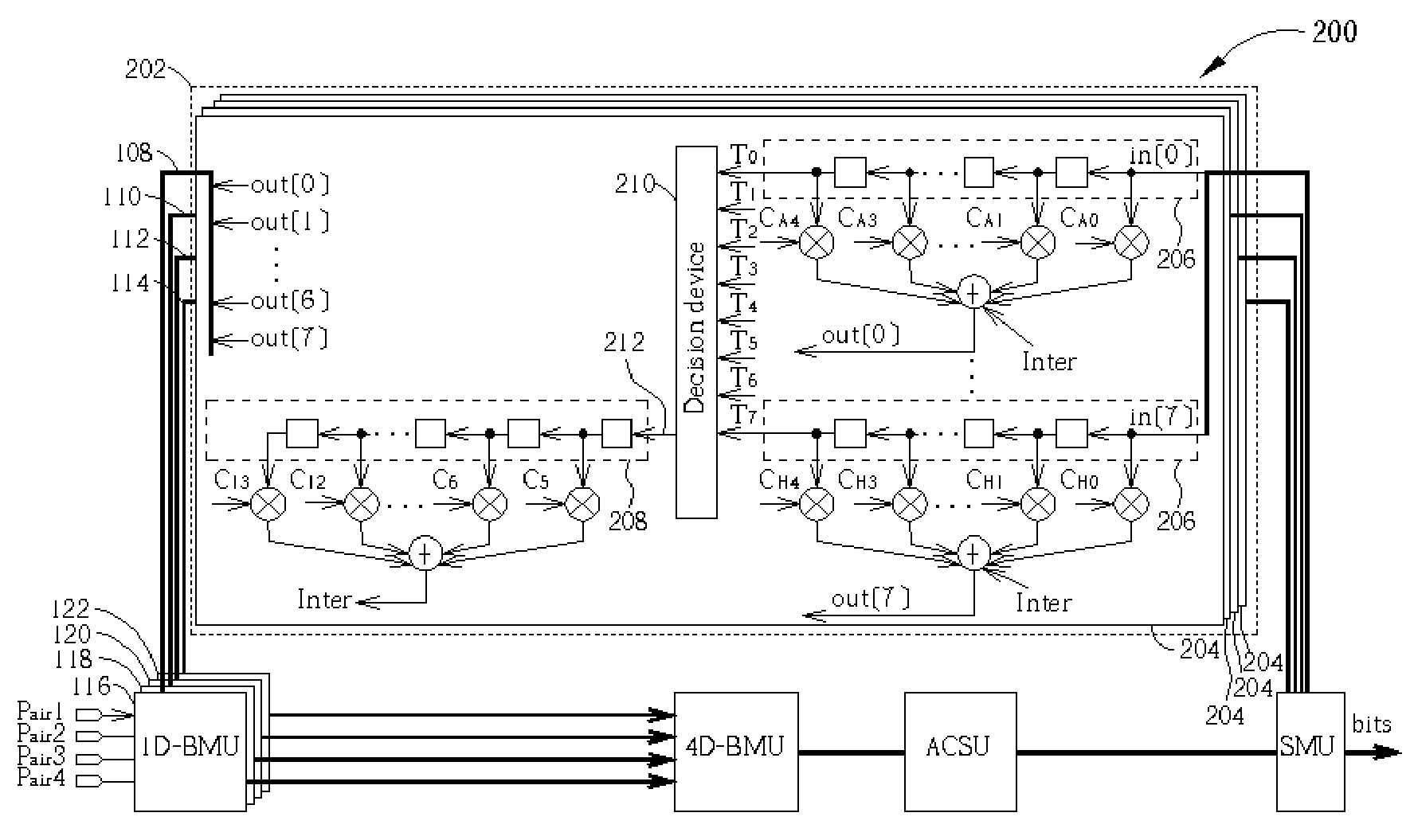
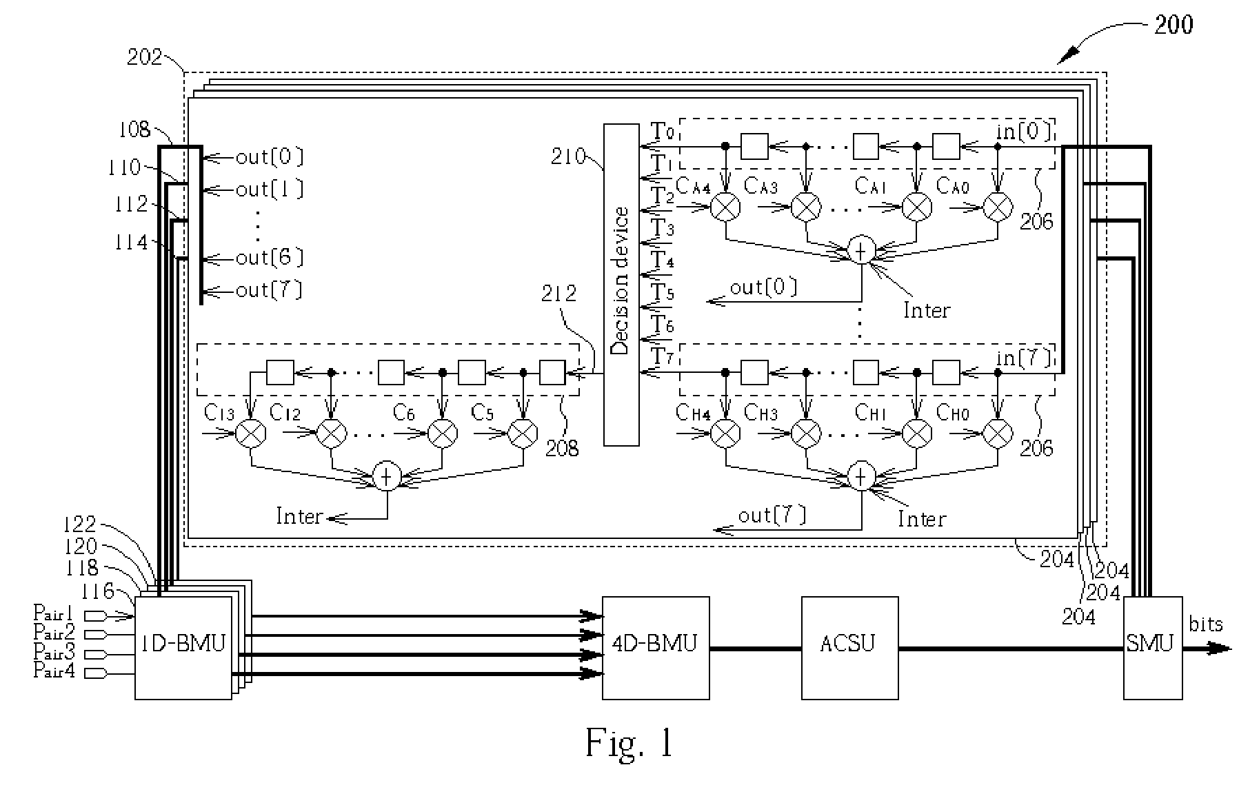
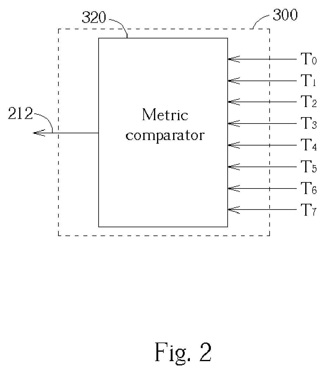
[0021]FIG. 2 is a block diagram detailing the implementation of a first embodiment decision device 300 for use as the decision device 210 of FIG. 1. The first decision device 300 compares the survivor metrics at the outputs T0, T1, T2, T3, T4, T5, T6, T7 of the state shift registers 206 shown in FIG. 1. The decision device 300 chooses a survivor metric 312 according to the survivor metrics at the last taps (i.e. the 5th taps) of the state shift registers 206. In this embodiment, the chosen survivor metric 312 outputted by the first decision device 300 is the survivor metric being present at the greatest number of outputs T0, T1, T2, T3, T4, T5, T6, T7 of the state shift registers 206. For example, if a particular survivor metric is received on outputs T0, T1, T3, T4, T6, and T7, this particular survivor metric has the most likelihood among others, is considered the most possible convergence, and is therefore chosen.

second embodiment

[0022]FIG. 3 is a block diagram detailing the implementation of a second embodiment decision device 400 for use as the decision device 210 of FIG. 1. The second decision device 400 includes an average unit 402 and a value selector 404. The average unit 402 simply averages the survivor metrics received on the outputs T0, T1, T2, T3, T4, T5, T6, T7 of the state shift registers 206. The average value 406 output by the average unit 402 is used by the value selector 404 to determine the appropriate survivor metric 212, which is then output by the second decision device 400. In this embodiment, the value selector 404 selects a survivor metric being closest to the average value 406. In this way, as long as there is a clear majority of states that have converged to the same survivor metric, the survivor metric 212 outputted by the second decision device 400 will resemble the survivor metric 212 outputted by the first decision device 300.

[0023] It will be evident to one having skill in the a...


PUM


Abstract

A P-tap parallel decision-feedback decoder (PDFD) is also disclosed. The PDFD includes a plurality of state shift registers. For each state of a code utilized by an incoming data stream, a survivor metric for a state is shifted into the first shift register for the state. Each first shift register has M cells. A decision device is coupled to the first shift registers for outputting a first survivor metric according to survivor metrics in the first shift registers. A second shift register has N delay cells, and the first survivor metric is shifted into the second shift register.

Description

BACKGROUND OF INVENTION [0001] 1. Field of the Invention [0002] The invention relates to data communications, and more particularly, to joint equalizing and decoding of an incoming data stream using a parallel decision-feedback decoder (PDFD). [0003] 2. Description of the Prior Art [0004] The IEEE 802.3ab standard for gigabit Ethernet, also termed 1000BASE-T, is now considered the future trend in local area network (LAN) applications. Gigabit Ethernet is defined as able to provide 1 gigabit per second (Gbps) bandwidth in combination with the simplicity of an Ethernet architecture, at a lower cost than other technologies of comparable speed. Moreover, gigabit Ethernet offers a smooth, seamless upgrade path for present 10BASE-T or 100BASE-T Ethernet installations. [0005] In order to obtain the requisite gigabit performance levels, gigabit Ethernet transceivers are interconnected with a multi-pair transmission channel architecture. In particular, transceivers are interconnected using f...

Claims


Application Information

Patent Timeline
IPC IPC(8): H03M13/00H03M13/03H03M13/41H04L5/00H04L25/03
CPCH03M13/4107H03M13/6502H04L2025/03426H04L2025/03363H04L2025/03369H04L25/03235
Inventor LIN, HOU-WEIKUO, SHIEH-HSINGYEN, KUANG-YUHO, JUNG-FENG
Owner REALTEK SEMICON CORP
Learn More