
Powder applicator for teeth

a powder applicator and tooth technology, applied in the field of orientation independent, can solve the problems of affecting the attainment of acceptable, affecting the success of existing powdering systems, and consuming too much powder,

Inactive Publication Date: 2005-10-20
HAMMAN JAMES EDWARD
View PDF13 Cites 25 Cited by
  • Summary
  • Abstract
  • Description
  • Claims
  • Application Information

AI Technical Summary

Benefits of technology

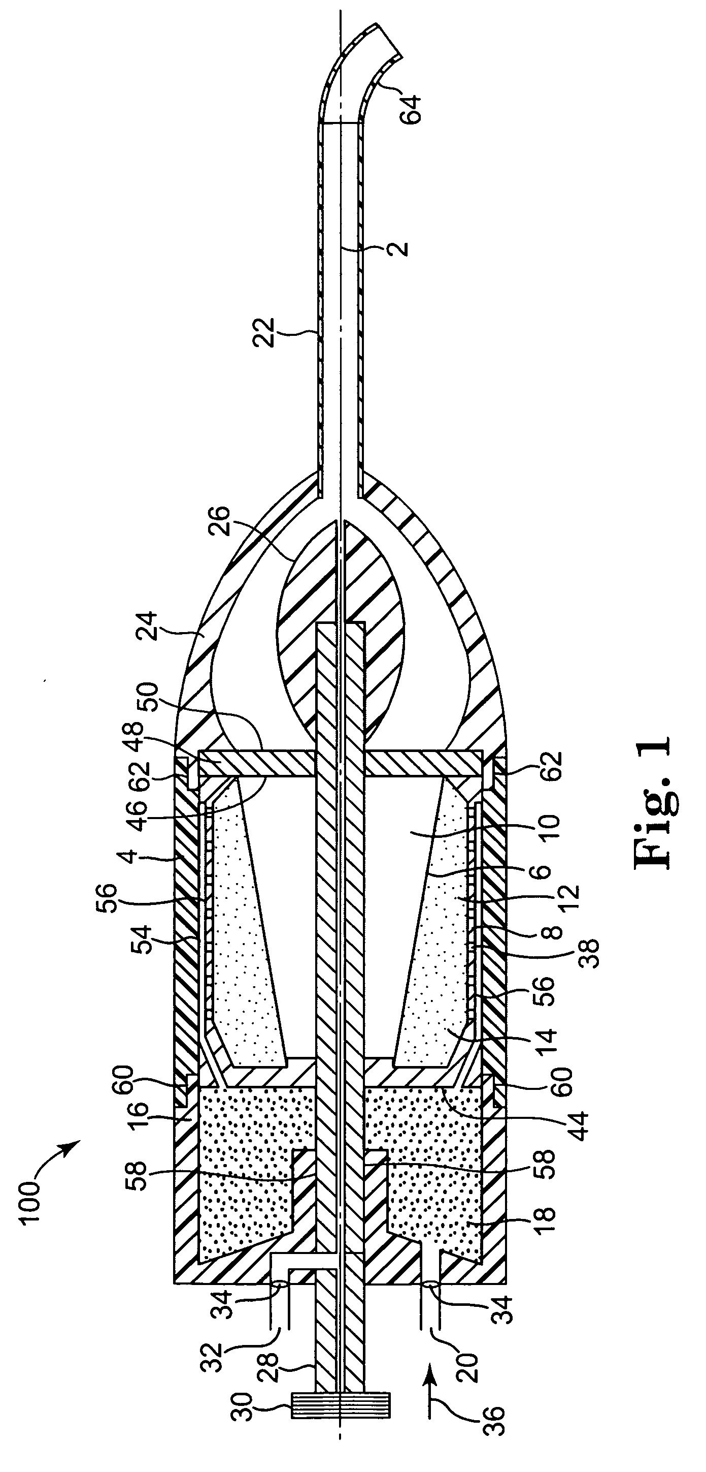
[0018] In yet another embodiment of the present invention is a method of delivering dental powder to a dental site. Delivery of the dental powder includes the steps of introducing pressurized air into a desiccant chamber of an orientation independent dental powder applicator through a first air input opening and desiccating the pressurized air. The method further includes the steps of directing the desiccated pressurized air into a powder reservoir and then circumferentially fluidizing the dental powder contained in the powder reservoir with the desiccated pressurized air. The fluidized dental powder and desiccated pressurized air is then directed towards an applicator tube along a longitudinal axis of the orientation independent dental powder applicator. The fluidized dental powder and desiccated pressurized air is additionally directed through the applicator tube, the applicator tube having a distal end directed towards the dental site facilitating application of the dental powder on the dental site.

Problems solved by technology

Problems with powdering devices, however, such as clogging, moisture contamination of the imaging powder and limited range of use interfere with the attainment of acceptable results during imaging and digitizing of the dental site.
Too much powder is a problem as is too thin a coat.
Existing powdering systems have attempted to overcome these problems with limited success.
Difficulties were encountered with the butane propellant device, however, when trying to achieve uniform and even application of the powder in remote locations of the mouth.
Because the butane propellant device uses an outlet stem that bends when contacted against the cheek, the user of the device had to force the cheek away using a second hand or additional device, which added further complexity to the powdering process.
Tilting the powder reservoir in the powdering device, however, leads to sporadic powder flow, clumping of the powder and ultimately clogging of the powdering device.
Water in the pressurized source of air poses a further problem with the POWDERMEISTER as the water will cause the powder to clump.
An additional problem with the POWDERMEISTER device is introduced by a thumbscrew controlled air valve on the container.
Some dentists find that thumbscrews turn too freely.
Despite this, the POWDERPERFEKT design is still prone to clogging for several reasons.
Second, the POWDERPERFEKT device depends upon the pressurized air line to be dry between the air compressor and desiccant only and does not address the need for keeping the powder dry between uses or ensuring that the air supply is dry prior to contact with the dental powder.
This is because the design of the POWDERPERFEKT device directs the path of air down into the powder where it disperses and aerolizes the dental powder inefficiently by causing large drifts of the dental powder to form necessitating physical agitation or tapping of the powder container to keep the powder in the path of the air stream.
There is also a large discrepancy between the volume of gas and fluidized material in the powder container and the small orifice that it exits.
This discrepancy leads to an abrupt change in velocity of the powder stream resulting in clogging.
Finally, there are limitations respecting angles that the disclosed device can be tilted during use before the dental powder jams.
Fourth, the intrinsic nature of the air control button to initiate the powder flow is too course to allow sufficient fine control of the airflow.
Thus, the air pressure flowing through the powder chamber is high and not adjustable, which leads to excessive powder application.

Method used


Image

  • Powder applicator for teeth
  • Powder applicator for teeth
  • Powder applicator for teeth

Examples


Embodiment Construction

[0041] The present invention provides an orientation independent apparatus for applying a uniform coating of a dental powder. In one embodiment of the present invention, orientation independent refers to the ability to position the longitudinal axis of the apparatus at any angle relative to a dental site.

[0042] The present invention is also related to a method of operating the orientation independent apparatus. The present invention can be used in the preparation of a replica tooth during restorative dental work. In particular, the present invention can be used to provide a uniform, very thin coating of consistent thickness of a contrast medium, such as a reflective powder like titanium dioxide (TiO2) or other suitable dental powder or imaging medium, to an area to be scanned by an infrared laser camera system or other such scanning devices such as the dental CAD / CAM restoration design and fabrication equipment in the Seimens (Sirona) CEREC machine series I, II, and III.

[0043] The...


PUM


Abstract

The present invention provides an orientation independent apparatus for applying a uniform coating of a dental powder as well as a method of operating the orientation independent apparatus. The present invention can be used in the preparation of a replica tooth during restorative dental work. Included in the present invention is an orientation independent dental powder applicator with a powder reservoir having an introductory circumferential plenum chamber, inner circumferential chamber and outer circumferential plenum chamber. Desiccated pressurized air enters the powder reservoir from a desiccant chamber and fluidizes dental powder located in either the inner circumferential chamber or outer circumferential plenum chamber. The powder reservoir is designed to allow pressurized air to flow around the entire perimeter of either the inner circumferential chamber or outer circumferential plenum chamber. The fluidized dental powder then travels into an acceleration chamber and ultimately through an applicator tube directed at a dental site.

Description

FIELD OF THE INVENTION [0001] The present invention relates to an orientation independent, dental powder applicator and a method of delivering dental powder to a dental site. The present invention can be used, for example, to apply a dental powder such as a contrast medium for imaging of a dental site. BACKGROUND OF THE INVENTION [0002] Restorative dental work includes making a replica tooth. The replica tooth is made based on the tooth to be restored. A traditional method of creating a replica tooth is to apply a pliable molding material around the tooth to be replaced. The cavity formed in the molding material by the tooth to be replaced can then be used to create a replica tooth of the desired dimensions and shape. More recent dental restoration techniques, however, utilize computer-aided methods. [0003] In order to capture a computer image of the tooth by an imaging device, the tooth is made to contrast with the rest of the patient's mouth by coating the surface of the tooth (al...

Claims


Application Information

Patent Timeline
IPC IPC(8): A61C3/02A61C3/025A61C9/00A61C17/00
CPCA61C9/004A61C3/025A61C9/0053
Inventor HAMMAN, JAMES EDWARD
Owner HAMMAN JAMES EDWARD
Learn More