
Printer with pivotable platen

Inactive Publication Date: 2005-10-20
BIXOLON
View PDF10 Cites 30 Cited by
  • Summary
  • Abstract
  • Description
  • Claims
  • Application Information

AI Technical Summary

Benefits of technology

[0021] An object of the present invention is to provide a printer with a pivotable platen, which is designed to easily remove a cover frame from a printer main body when it is intended to exchange a paper and to easily remove a paper jammed between the printer head and the platen by simply modifying a structure thereof.
[0022] Another object of the present invention is to provide a printer with a pivotable platen, which is designed to improve the printing quality by accurately aligning a paper and a ribbon between a printer head and a platen by allowing the paper to be stably disposed to a printing position during the paper loading operation.
[0023] Still another object of the present invention is to provide an inexpensive printer that is improved in function and quality.

Problems solved by technology

While no gap exists between the printer head and the paper in the direct thermal printer, there is a relatively wide gap between the printer head and the paper in the inkjet printer.
However, in the impact dot printer, a gap between the printer head and the platen is very important for the printing quality.
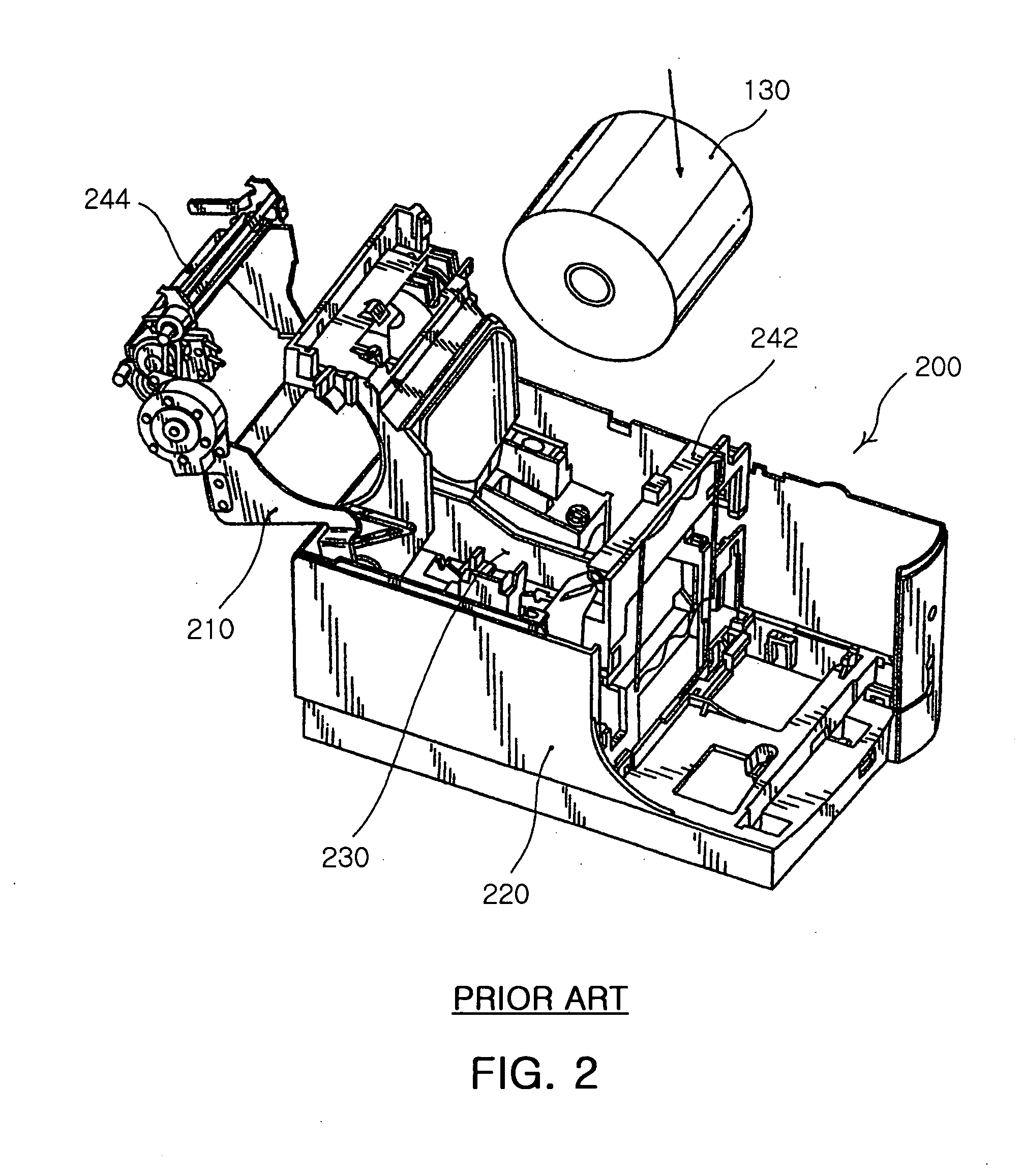
However, since the platen is integrally fixed on the pivotable cover frame 210, it is frequently incurred that the paper 130 and the ribbon 122 are jammed in a narrow gap between the printer head and the platen.
Furthermore, since the platen conflicts frequently with frame components, the opening / closing operation may not be effectively realized.
Since the easy paper load and easy jammed paper removal are still very important for the dot printer when considering the use and management of the printer, there is still problems in the drop and printing-type or clamshell-type impact dot printer.
A structure relating to the reciprocating motion of the platen roller is very complicated, making it difficult to manufacture the same and increasing the manufacturing costs.
Therefore, it is difficult to apply the structure of the inkjet printer to the impact dot printer where a ribbon is inserted between the printer head and the platen roller.

Method used


Image

  • Printer with pivotable platen
  • Printer with pivotable platen
  • Printer with pivotable platen

Examples


Embodiment Construction

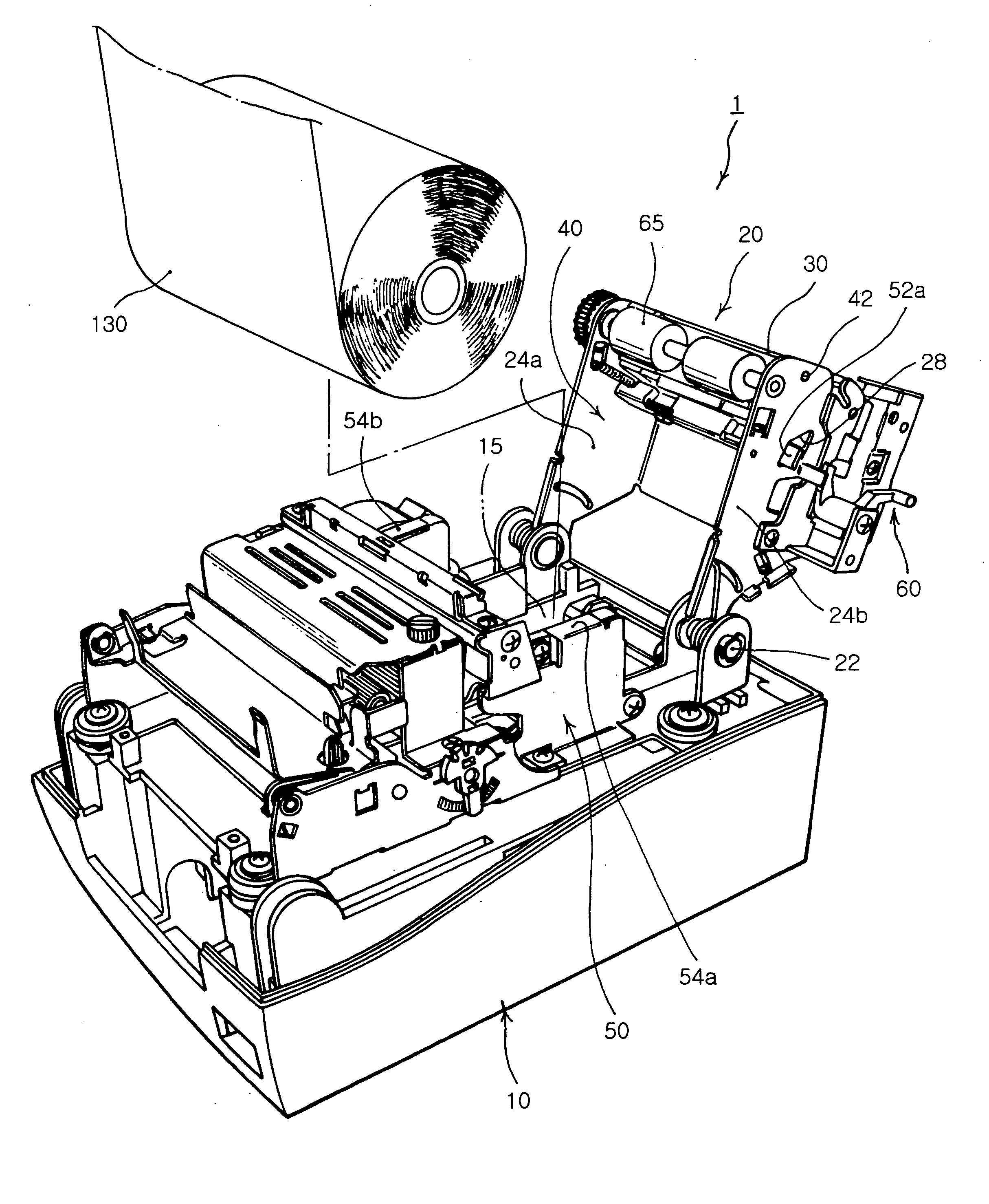
[0036] Reference will now be made in detail to the preferred embodiments of the present invention, examples of which are illustrated in the accompanying drawings.

[0037] FIGS. 3 to 5 show a printer according to an embodiment of the present invention. The inventive printer is exampled as a dot printer, and may be applied to an electronic cash register or a point of sales system and formed in a drop and printing type or a clamshell type where a roll type paper 130 can be easily loaded in a printer main body 10. However, the dot printer that will be described in this embodiment is exemplary only. That is, a feature of the present invention is applied to not only such a dot printer 1 but also other types of printers such as an inkjet printer and the like.

[0038] FIGS. 3 to 5 show an internal structure of the inventive dot printer 1 by eliminating a cover.

[0039] The dot printer 1 is designed to load the paper 130 in a loading space 15 of the printer main body 10 after a cover frame 20 i...


PUM


Abstract

A printer for an electronic cash register or a point of sales system includes a printer main body having a printer head, a cover frame pivotally connected to the printer main body, and a platen adjusting unit. A platen is mounted on an end of the cover frame. The platen adjusting unit is designed to allow the platen to pivot away from the printer head when the cover frame is opened, and to allow the platen to pivot close to the printer head with a predetermined gap between the platen and the printer head when the cover frame is closed.

Description

RELATED APPLICATION [0001] The present application is based on, and claims priority from, Korean Patent Application Number 10-2004-0026118, filed 16 Apr., 2004, the disclosure of which is hereby incorporated by reference herein in its entirety. BACKGROUND OF THE INVENTION [0002] 1. Field of the Invention [0003] The present invention relates to a printer applicable to an electronic cash register or a point of sales (POS) system, and more particularly, to a printer with a pivotable platen, which is designed to avoid a confliction between the platen and peripheral components by allowing the platen to be pivoted away from a printer head; to improve the printing quality by allowing the platen to be close to the printer head when a cover frame is closed; to easily remove a paper jammed between the printer head and the platen; and to provide convenience in use by allowing papers to be stably loaded. [0004] 2. Description of the Related Art [0005] In an electronic cash register or a point o...

Claims


Application Information

Patent Timeline
IPC IPC(8): B41J11/02B41J11/04B41J11/14B41J15/04
CPCB41J11/04B41J15/042B41J11/14B41J2/325
Inventor NA, KYOUNG HWANNAM, SANG IK
Owner BIXOLON
Learn More