
Method and apparatus for filtering particulate matter from an air-flow

a technology of airflow and filtering method, applied in the field of filtration, can solve the problems of reducing the airflow through the filter, reducing the efficiency of the filter, and only capturing larger particles, and achieve the effect of reducing the back-pressure of the filter

Inactive Publication Date: 2005-10-20
BROWN JEFFREY A +1
View PDF16 Cites 79 Cited by
  • Summary
  • Abstract
  • Description
  • Claims
  • Application Information

AI Technical Summary

Benefits of technology

[0015] Therefore, in light of the above, and for other reasons that may become apparent when the invention is fully described, an object of the present invention is to reduce filter back-pressure associated with filtering small particles from an air-flow.
[0016] Another object of the present invention is to maintain reduced filter back-pressure despite loading of a filter with trapped particles.
[0017] Yet another object of the present invention is to maintain reduced filter back-pressure despite increases in air-flow velocities.

Problems solved by technology

Typically, however, viscous impingement filters only trap larger particles (e.g., greater than 5 μm) and do so with less efficiency (e.g., typically trapping less then 25%, by weight, of particles greater than 5 μm in diameter) than can be achieved using dry or HEPA filters.
However, the smaller the pore size of conventional filters, the greater the resistance to air-flow (i.e., the greater the pressure drop) typically introduced by a clean conventional filter to a stream of air flowing through the filter.
Hence, filters designed to capture smaller particles with a high degree efficiency are typically more susceptible to becoming clogged with particles filtered from the air-flow, thereby reducing air-flow through the filter and, hence, reducing the effectiveness of the filter in removing particles from the air-flow.
As conventional filters begin to collect particulate matter from the air they are filtering, their effectiveness immediately begins to decline.
Hence, a need remains for an apparatus and method capable of removing a broad range of particle sizes from an air-flow, yet that produces a low resistance to air-flow even when filtering air-flows with high velocities.

Method used


Image

  • Method and apparatus for filtering particulate matter from an air-flow
  • Method and apparatus for filtering particulate matter from an air-flow
  • Method and apparatus for filtering particulate matter from an air-flow

Examples


Embodiment Construction

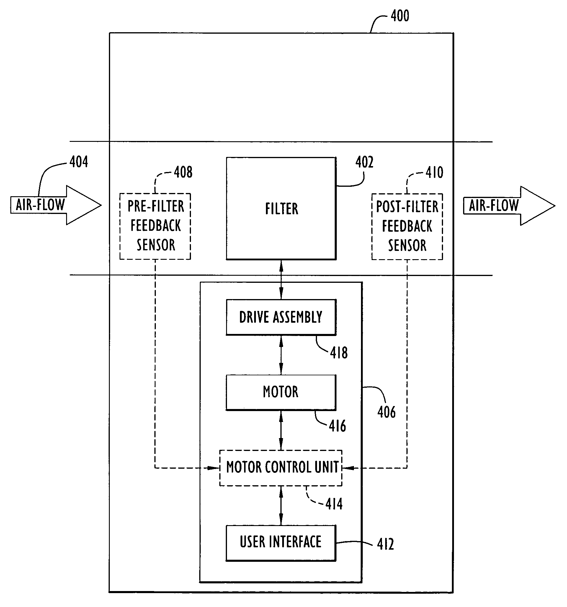
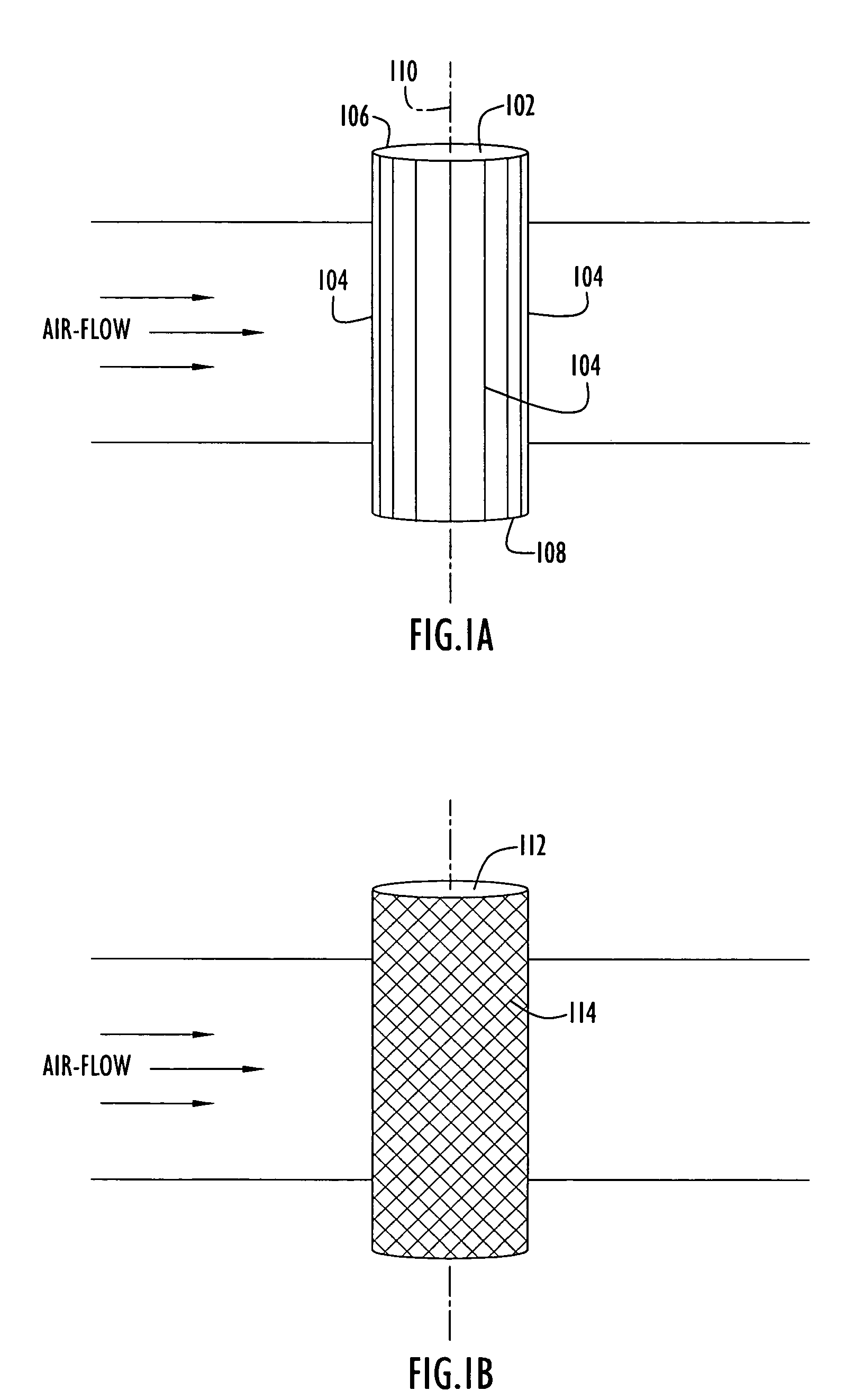
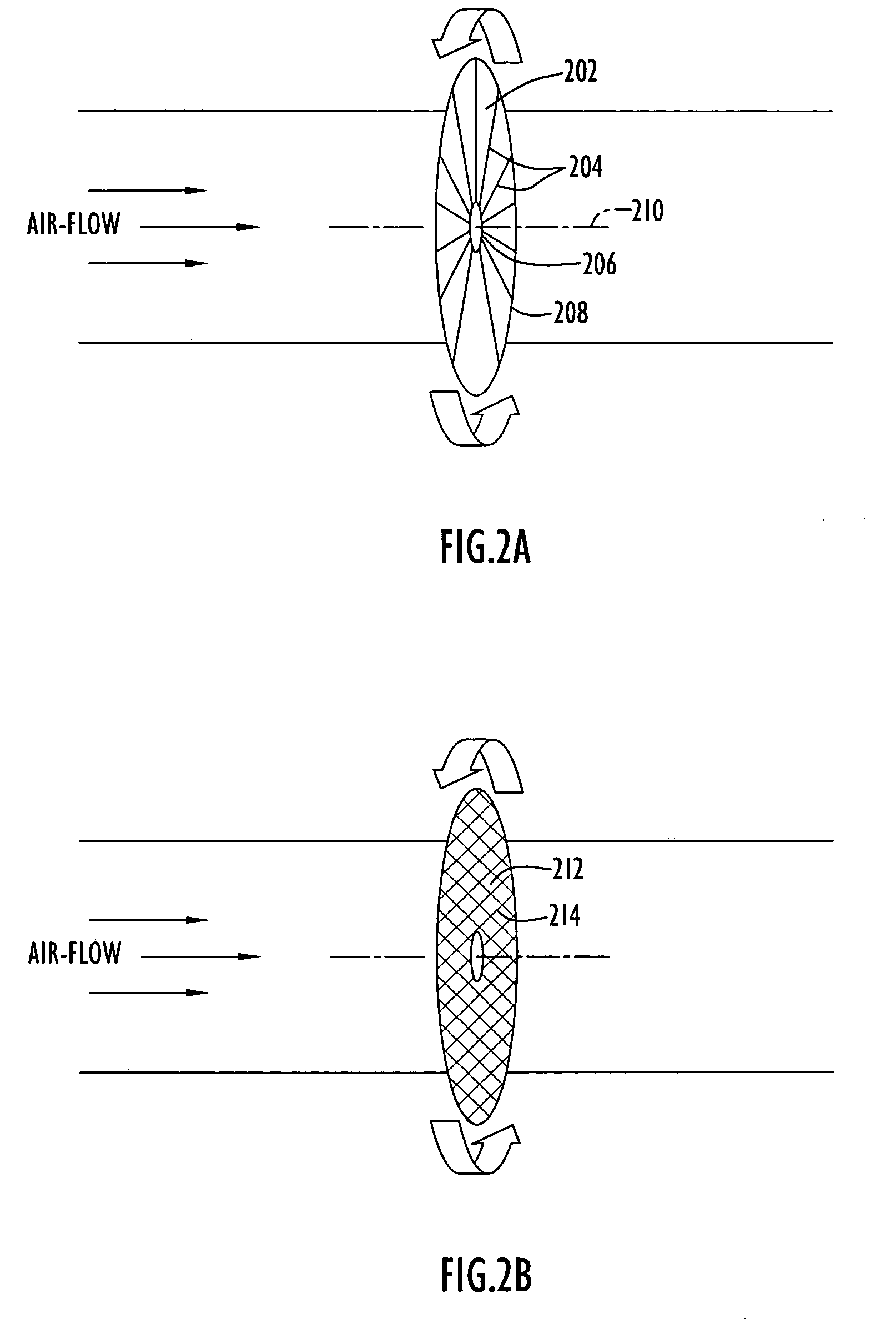
[0040]FIG. 1A and FIG. 1B are diagrammatic views of a cylindrical bar filter and a cylindrical mesh filter, respectively, that may be used to filter air flowing within a channel, or duct. In such an embodiment, the filter is in the shape of a substantially hollow right cylinder with a diameter (D) and a cylinder height (H). As shown in FIG. 1A, cylindrical bar filter 102 may include a set of parallel bars 104 that connect points on the perimeter of circular base 106 with corresponding points upon circular base 108, thereby forming a right cylinder balanced about a central axis 110. Cylindrical bar filter 102 may be inserted directly within a rectangular air channel, or duct, with a length (L) that is only slightly greater (e.g., 0.5 cm) than cylinder height (H), and a width (W) that is only slightly greater (e.g., 0.5 cm) than the diameter (D) of cylindrical bar filter 102. Optionally, cylindrical bar filter 102 may be housed within a separate housing that may be connected within th...


PUM

PropertyMeasurementUnit
Sizeaaaaaaaaaa
Speedaaaaaaaaaa
Areaaaaaaaaaaa

Abstract

A method and apparatus is described for removing particles from an air-flow. An air-flow containing microscopic particulate matter is passed through a filter that rotates or oscillates at a high rate of speed relative to the speed of the air-flow and in a direction substantially perpendicular to the direction of the air-flow. The filter in motion impacts and thereby removes particulate matter from the air passing through it, yet the far smaller air molecules pass unimpeded through the mesh in the filter. The filter and filtration system maintain consistent operational performance despite changes in the condition of the filter and / or changes in the operational environment by adjusting the filter's speed and / or by cleaning the filter on a periodic or continuous basis. The effective life of a filter is extended, thereby increasing the period of time between filter replacements and reducing life-cycle man-power and material costs without any sacrifices in performance.

Description

BACKGROUND OF THE INVENTION [0001] 1. Field of the Invention [0002] The present invention pertains to filtration. In particular, the present invention pertains to filtering particulate matter from an air-flow using a filter placed in motion. [0003] 2. Description of the Related Art [0004] Particulate matter (PM) is the general term used for a mixture of solid particles and / or liquid droplets found in the air. These particles, which come in a wide range of sizes, may be emitted directly by a source or formed in the atmosphere. Particles suspended within the air in domestic, commercial and industrial environments typically range in size from less than 0.01 μm (e.g., smokes) to as high as 45 μm (e.g., dust, pollen spores, emissions from industrial processes, etc). Table 1, below, presents a representative distribution of particle sizes that may be suspended within the atmosphere in a domestic, commercial or industrial environment. In addition to the particle sizes listed in Table 1, ev...

Claims


Application Information

Patent Timeline
IPC IPC(8): B01D46/26B01D46/46
CPCB01D46/0072B01D46/44B01D46/10B01D46/74
Inventor BROWN, JEFFREY A.DROZDOV, ALEXEI
Owner BROWN JEFFREY A
Learn More