
Maxillary molar distalization jig

a maxillary molar and jig technology, applied in the field of orthodontic appliances, can solve the problems of increasing treatment duration, reducing treatment success, and easy loss of anchorage, and achieve the effect of improving intraoral applian

Inactive Publication Date: 2005-10-06
KELES AHMET OZLEM
View PDF6 Cites 17 Cited by
  • Summary
  • Abstract
  • Description
  • Claims
  • Application Information

AI Technical Summary

Problems solved by technology

However, if the maxillary molars are not distalized bodily and adequate anchorage is not established to move premolars and canines distally, anchorage will be lost very easily.
However, headgear totally relied on patient cooperation, which could reduce treatment success and increase treatment duration.
On the other hand, headgear was rejected by many patients because of aesthetic and social concern.
Their results showed that the molars distalized without tipping; however, the expense of bodily distalization was significant anchorage loss.
Due to the complicated nature of prior art devices, chair side construction and installation of the orthodontic appliances were not possible or at least very difficult.
Furthermore, the disclosed acrylic material construction was restricted to the laboratory environment.
Chemical cure orthodontic acrylic cannot be used directly in the user's mouth because of toxicity of metil metacylate.
A user would require impressions to be taken of the user's mouth and a waiting period for return of the hardened acrylic orthodontic appliance from the laboratory, and installations could take multiple visits because adjustments could not always be made chair side.

Method used


Image

  • Maxillary molar distalization jig
  • Maxillary molar distalization jig
  • Maxillary molar distalization jig

Examples


Embodiment Construction

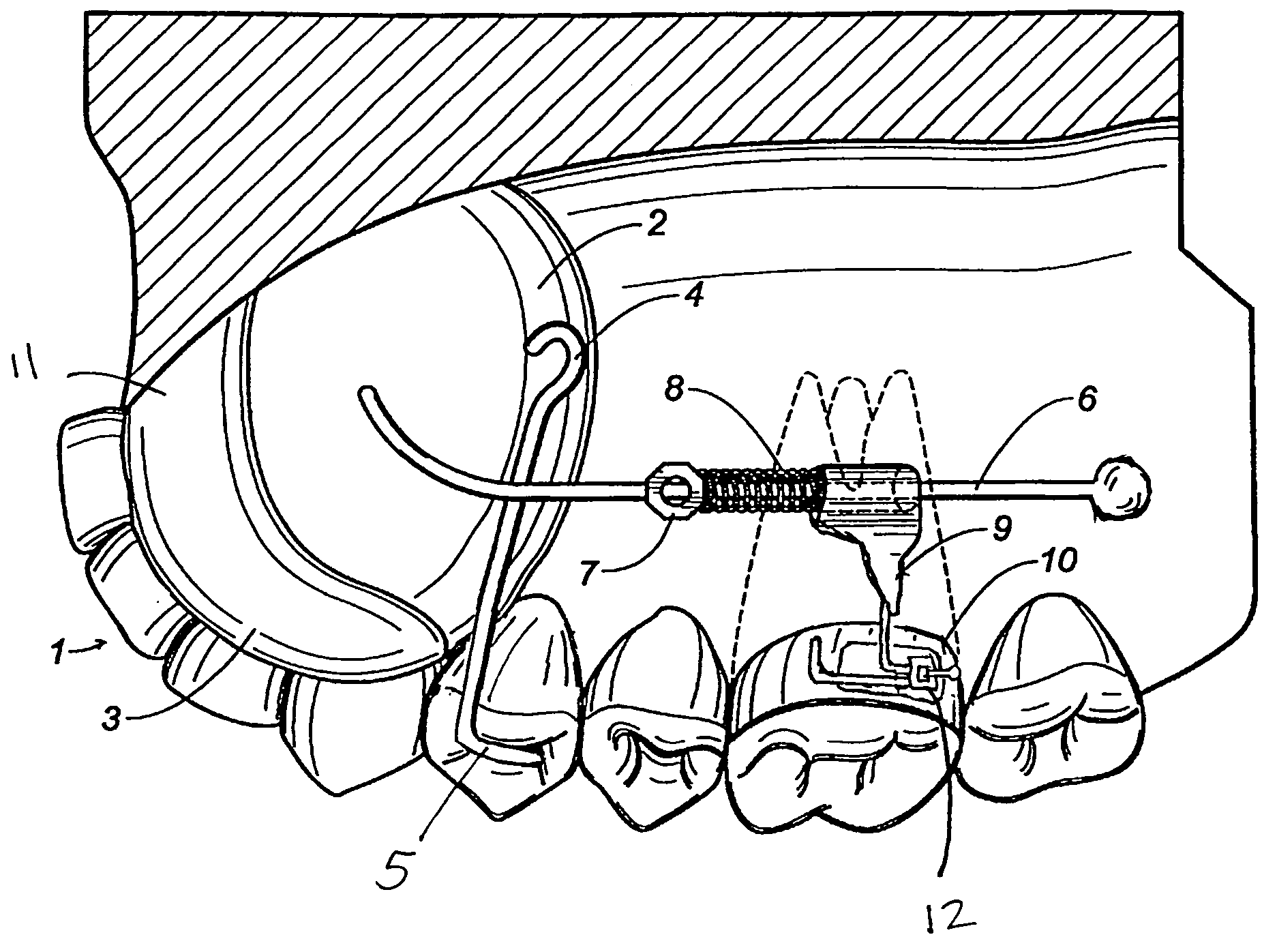
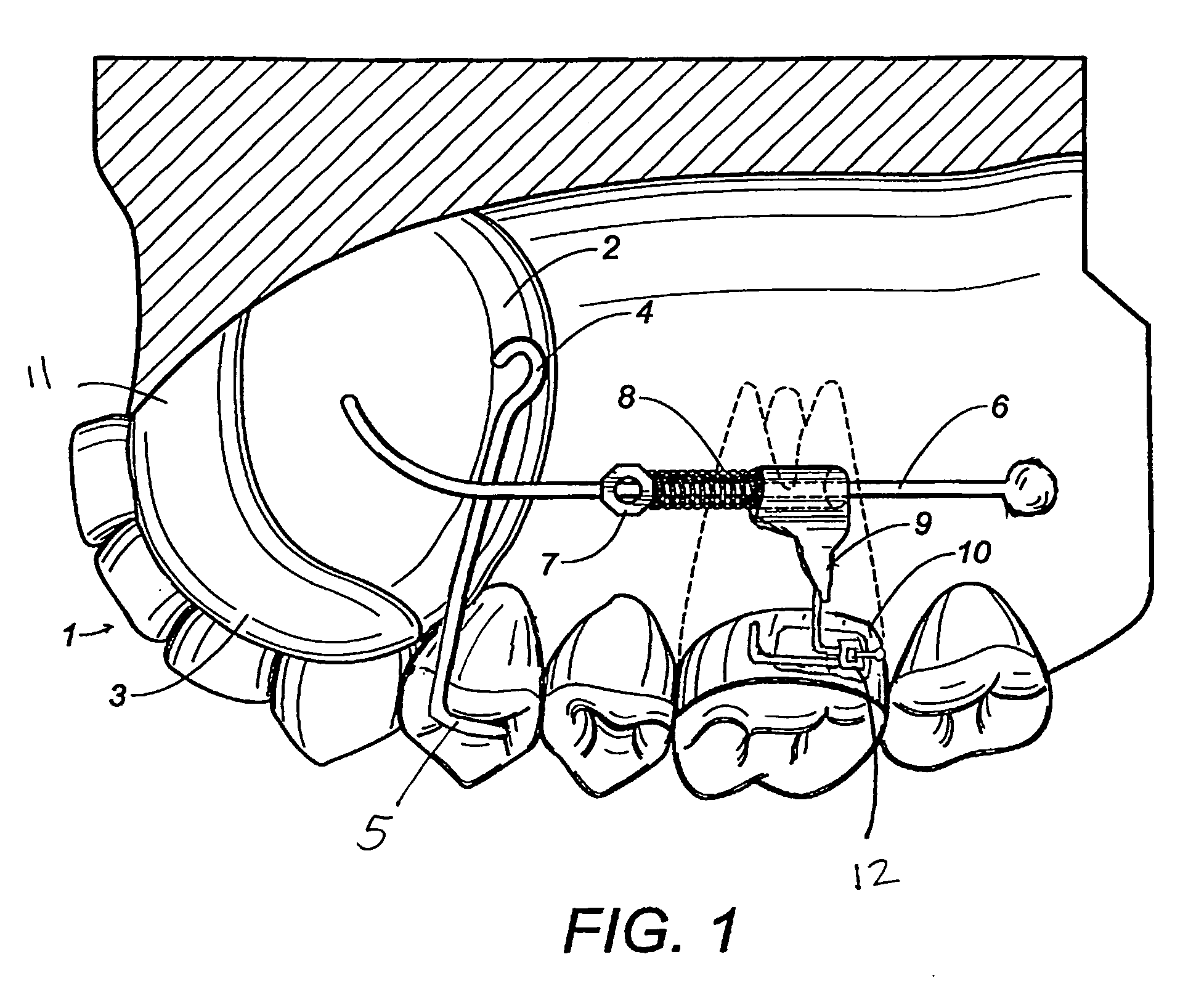
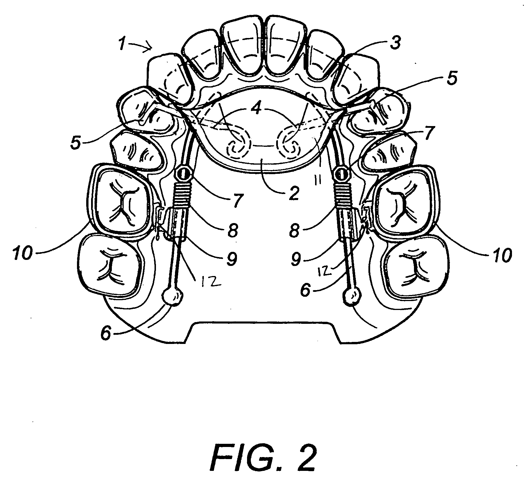
[0021] Referring to FIGS. 1-3, the present invention is an orthodontic appliance. FIG. 1 shows a lateral palatal view with the appliance installed in a user's mouth, and FIG. 2 is the occlusal view of the present invention shown in FIG. 1. FIG. 3 shows several individual parts of the orthodontic appliance of the present invention.

[0022] As shown in the Figures, the orthodontic appliance 1 of the present invention includes an acrylic support plate 11 with a Nance button 2 and an anterior bite plane 3. The acrylic support plate 11 is comprised of acrylic material constructed during installation of the support plate 11. There is a plurality of retaining wires 4 extending from the acrylic support plate 11. These retaining wires are attached to the first premolar teeth of the user's mouth with bonding material chair side at bonding ends 5. The retaining wires 4 are bonded directly chair side on the chewing surface of the first premolar teeth by respective bonding ends 5, while the oppos...


PUM


Abstract

An orthodontic appliance for use in a mouth of a user has an acrylic support plate with a wide Nance button and an anterior bite plane, a plurality of retaining wires, a plurality of rigid wire rods, a lock, a coil spring, a tubular member and first molar bands. The acrylic support plate has the retaining wires extending therefrom and is made of acrylic material constructed during installation of the support plate. The first premolar teeth are fixedly attached to the retaining wires chair side. The first molar bands are removably attached to each wire extension of respective tubular member. When the coil spring is compressed between the acrylic support plate and the tubular member by tightening the lock, the tubular member moves in a distal direction by force of the coil spring. The force is aligned with centers of resistance of molars in the mouth of the user.

Description

RELATED U.S. APPLICATIONS [0001] Not applicable. STATEMENT REGARDING FEDERALLY SPONSORED RESEARCH OR DEVELOPMENT [0002] Not applicable. REFERENCE TO MICROFICHE APPENDIX [0003] Not applicable. FIELD OF THE INVENTION [0004] This invention is related to an orthodontic appliance, specifically a maxillary molar distalization jig, which moves the maxillary molars back and corrects their positions. BACKGROUND OF THE INVENTION [0005] Over the past ten years non-extraction treatment and non-compliance therapies have become more popular in correction of Class II malocclusions. Treatment of Class II cases usually requires distal movement of maxillary molars in order to achieve Class I molar and canine relationship. However, if the maxillary molars are not distalized bodily and adequate anchorage is not established to move premolars and canines distally, anchorage will be lost very easily. In the literature, various types of devices were developed for molar distalization. For years headgear was...

Claims


Application Information

Patent Timeline
Patent Type & Authority Applications(United States)
IPC IPC(8): A61C3/00A61C7/00
CPCA61C7/00A61C7/10
Inventor KELES, AHMET OZLEM
Owner KELES AHMET OZLEM
Learn More