
Fuel cell apparatus

a fuel cell and apparatus technology, applied in the field of fuel cells, can solve the problems of clogging fuel and air passages, affecting the rated output of the fuel cell, so as to reduce the potential for water freezing in the channel

Inactive Publication Date: 2005-10-06
NISSAN MOTOR CO LTD
View PDF6 Cites 2 Cited by
  • Summary
  • Abstract
  • Description
  • Claims
  • Application Information

AI Technical Summary

Benefits of technology

[0006] An advantage of the present invention is an improved fuel cell having a water channel which minimizes the potential for water freezing in the channel.
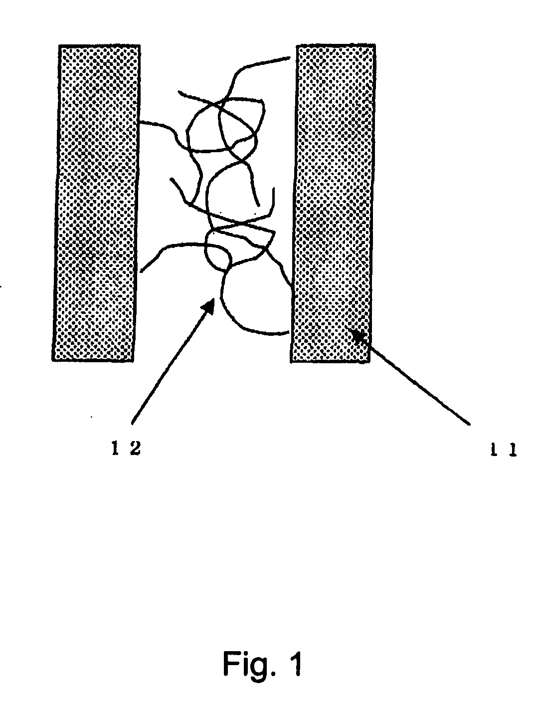
[0007] These and other advantages are satisfied at least in part by a fuel cell having a water channel which contains a polymeric material attached to the walls of the channel. In an embodiment of the present invention, the fuel cell is characterized by having a pure water channel comprising polymers, wherein one end of the polymer chains are connected to a surface of the channel and said chains are capable of forming an entanglement among themselves. Advantageously, such a structure permits water contained in the channel to be bound by the polymer material through polymeric entanglements thereby minimizing the potential for the water to freeze when the cell is not in operation. When the cell is operated, the flow of water and / or the increase in temperature of the cell causes the polymeric material to disentangle thereby allowing water to flow through the channel during normal operation.
[0008] The fuel cell can further comprise a means for discharging excess water from the channel to outside of the cell when the cell is shut down and means for measuring at least the flow rate or at least the pressure of the water in the channel and a means for controlling the flow rate or pressure of the water in the channel so that it does not exceed a predetermined range.

Problems solved by technology

Consequently, if the fuel cell is in an environment of 0° C. or below, the pure water channel may be blocked, and the fuel and air passages may also be clogged due to frozen water.
If a fuel cell is started up in a frozen state, it may take a long time to reach the rated output, since it is necessary to melt the accumulated ice.
Alternatively, the interior of the fuel cell stack, which includes the polymer membrane, may be damaged, thereby worsening cell performance.
If the pure water channel has a humidifying or cooling function, it cannot perform these functions when the fuel cell is started up, since there is no pure water in the channel after discharge.
Therefore, when the fuel cell is restarted, it is necessary to re-supply the water channel with pure water, because recirculated water alone is not enough.
In addition, discharging a large quantity of water from the fuel cell has other disadvantages.
For instance, given a fuel cell for automotive use, there is the risk of causing the road to ice over if a large quantity of pure water is discharged to the outside environment at sub-zero temperatures.
However, since the pure water in the reservoir tank also freezes, it is necessary to melt the ice in the reservoir tank when re-starting.
This lengthens the time required for startup, and increases the fuel consumption due to the utilization of a heater.

Method used


Image

  • Fuel cell apparatus
  • Fuel cell apparatus
  • Fuel cell apparatus

Examples


example 1

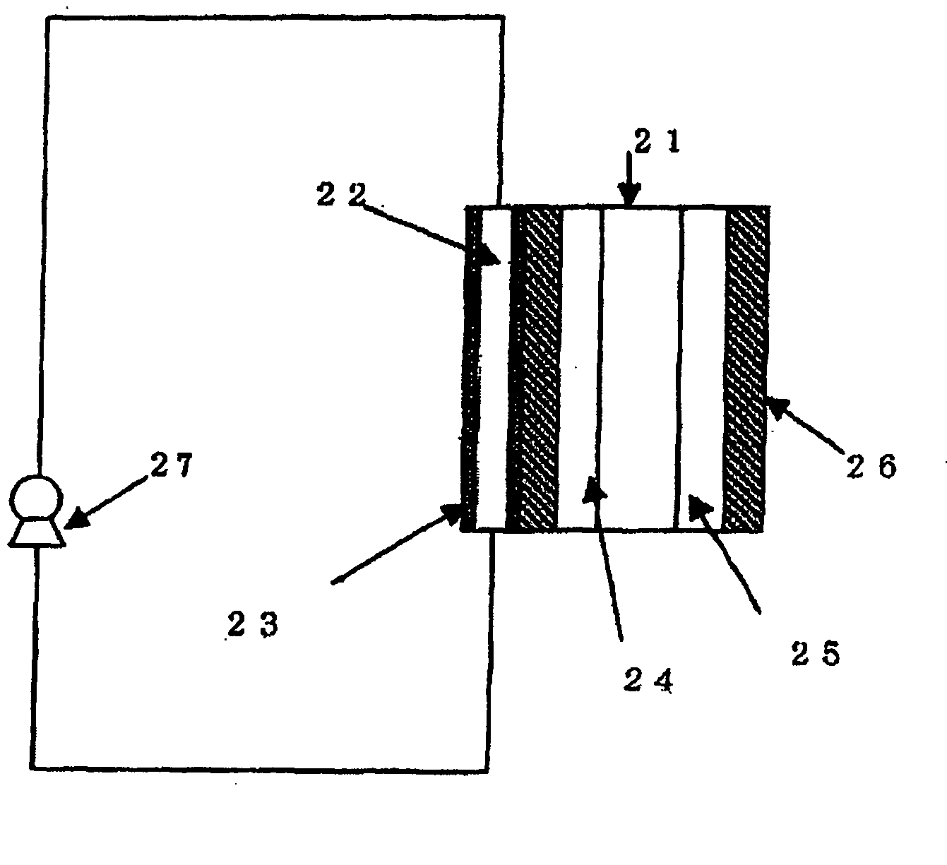
[0037] In this example, a fuel cell stack having cells with a basic structure shown in FIG. 2 was used. The cells differ in that one end of N-isopropyl acrylamide is connected to the surface of the pure water channel rather than PMMA. The N-isopropyl acrylamide was attached to the channel wall by plasma polymerization. This fuel cell stack was operated by the procedure shown in FIG. 6. After startup at room temperature, the cell is operated at about 70° C., and is subsequently shut down. After shutdown, the atmospheric temperature surrounding the fuel cell is lowered to −20° C. The N-isopropyl acrylamide undergoes volume phase transition at about 40° C., and expands in the pure water channel. After maintaining the cell for 8 hours at −20° C., dried hydrogen gas and air at 40° C. were caused to flow, which caused the cell to start generating electricity again. At the stage where the fuel cell temperature reaches 40° C., pure water starts to circulate. Due to the rise in fuel cell tem...

example 2

[0038] In this example, a fuel cell having the basic cell structure as shown in FIG. 3 was used. In addition to the implementation of example 1, three-way valve 30, three-way valve 31 and blower 32 are set in the coolant loop. Pressure gauge 34 and pressure gauge 36 are set to control pressure control valve 33 and pressure control valve 35 through pressure controller 37. During operating the fuel cell system, three-way vale 30 and three-way valve 31 are set as follows to make a loop.

Three-way valve 30Three-way valve 31Line A: OpenedLine D: OpenedLine B: OpenedLine E: OpenedLine C: ClosedLine F: Closed

[0039] First, three-way vale 30 and three-way valve 31 are set as follows to drain water from the fuel cell stack when the fuel cell system is shut down.

Three-way valve 30Three-way valve 31Line A: OpenedLine D: OpenedLine B: ClosedLine E: ClosedLine C: OpenedLine F: Opened

[0040] Secondly, blower 32 starts to drain water from fuel cell stack. Blower 32 stops after a predetermined tim...


PUM


Abstract

A fuel cell is disclosed having a water channel and a polymeric material contained in the water channel which minimizes freezing of water in the channel at sub-zero temperatures. Embodiments including attaching a thermo-responsive polymer such as an N-isopropyl acrylamide to the surface of the water channel to cause the thermo-responsive polymer to expand at low temperatures thereby reducing the propensity for water to freeze in the channel and also to cause the thermo-responsive polymer to contract at higher temperatures thereby preventing any restriction in the flow of circulating water in the channel.

Description

FIELD OF THE INVENTION [0001] The present invention generally relates to fuel cells, and more particularly to improvements in the performance of polymer fuel cells having a water channel. BACKGROUND OF THE INVENTION [0002] In a fuel cell that contains a pure water channel, the water in the pure water channel freezes at temperatures of 0° C. and below. Consequently, if the fuel cell is in an environment of 0° C. or below, the pure water channel may be blocked, and the fuel and air passages may also be clogged due to frozen water. If a fuel cell is started up in a frozen state, it may take a long time to reach the rated output, since it is necessary to melt the accumulated ice. Alternatively, the interior of the fuel cell stack, which includes the polymer membrane, may be damaged, thereby worsening cell performance. [0003] One method of solving this problem is to discharge the pure water from the channel outside of the cell when the fuel cell is shut down. The water can be discharged ...

Claims


Application Information

Patent Timeline
IPC IPC(8): H01M2/02H01M8/04H01M2/14H01M2/00H01M8/10
CPCH01M8/04029H01M8/04253H01M8/04291H01M8/04417H01M8/04768Y02E60/50
Inventor TAKAHASHI, SHINICHI
Owner NISSAN MOTOR CO LTD
Learn More