Head cartridge and liquid ejection apparatus
a liquid ejection apparatus and cartridge technology, applied in printing and other directions, can solve the problems of insufficient removal of ink stuck in the ink ejection nozzle or its vicinity so as to thicken, and achieve the effects of increasing the elastic deformation of the wiping member, restoring the operation of the elastic deformation, and increasing the absorbing force of liquid
- Summary
- Abstract
- Description
- Claims
- Application Information
AI Technical Summary
Benefits of technology
Problems solved by technology
Method used
Image
Examples
first embodiment
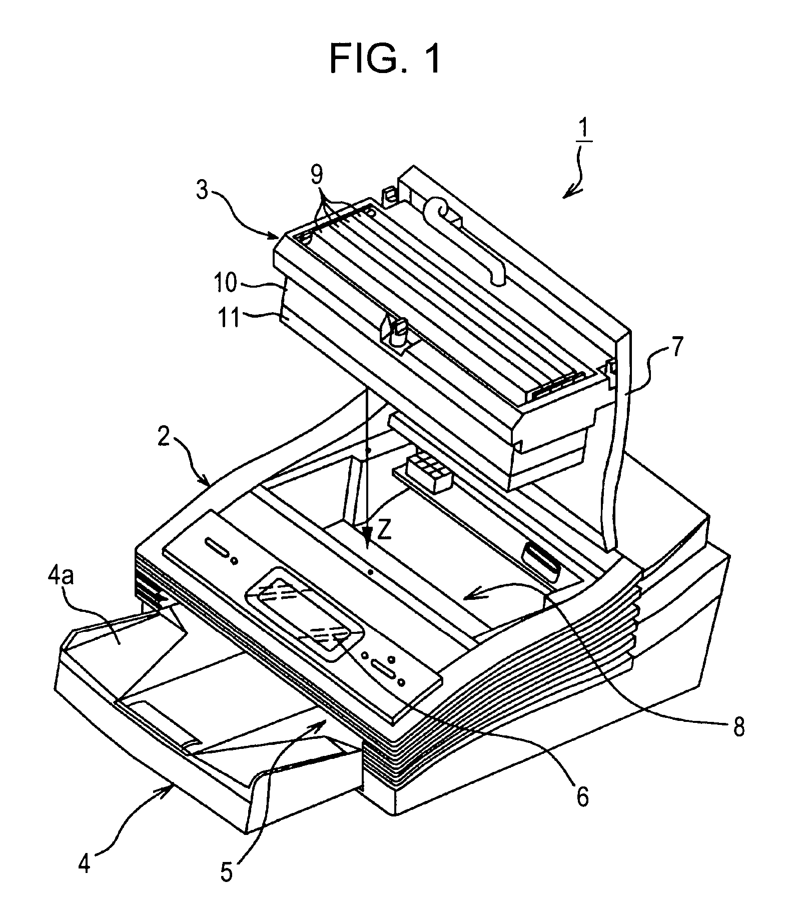
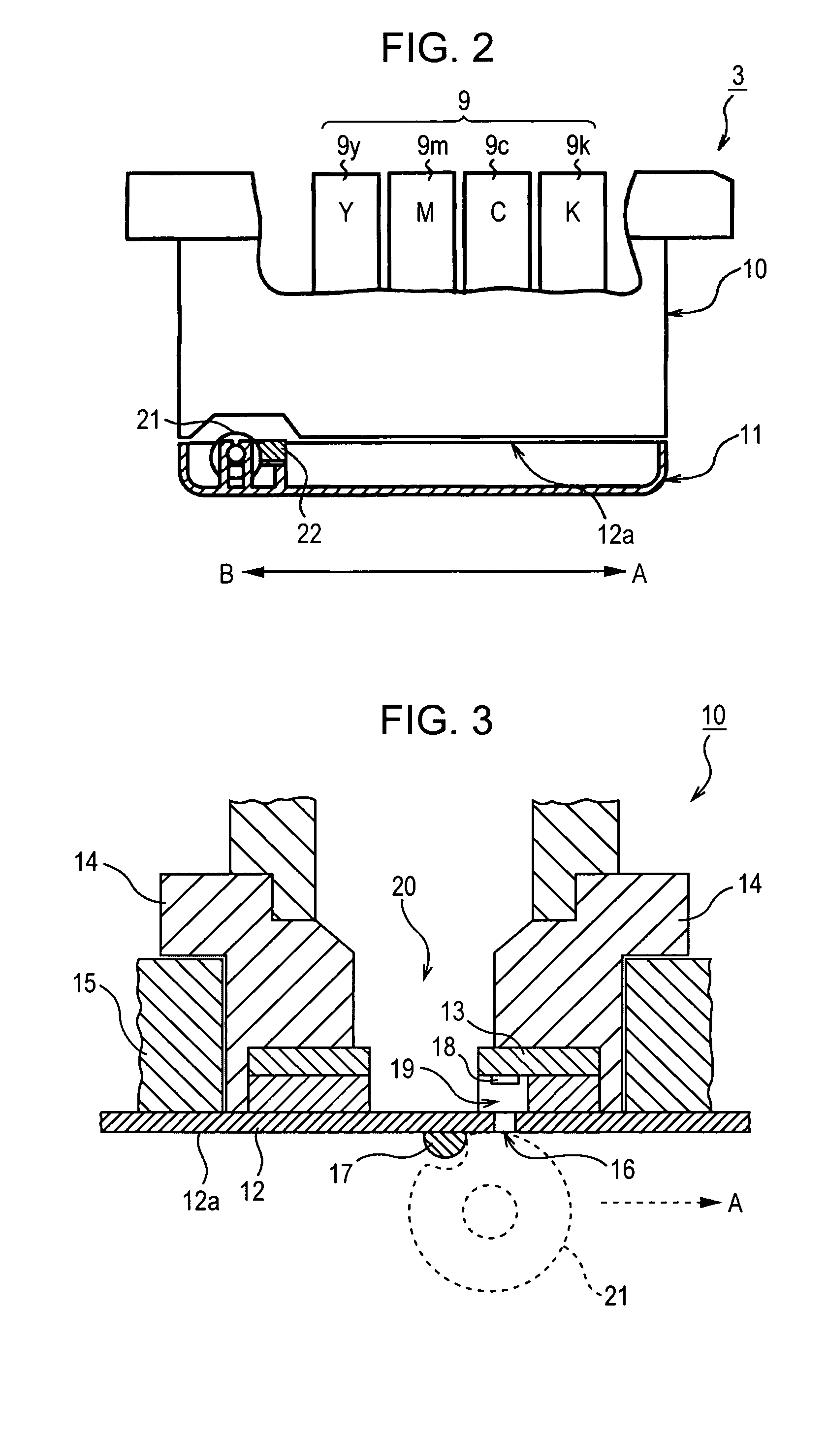
[0031] Then, the present invention of the head cartridge suitable for the inkjet printer will be described with reference to FIGS. 2 to 6.
[0032]FIG. 2 is a partially sectional side view of the head cartridge 3 shown in FIG. 1. Four ink tanks 9 (9y, 9m, 9c, and 9k) are loaded within the head cartridge 3. The ink tank 9 is a liquid container for storing ink, so that the respective ink tanks 9 contain the four color inks of Y, M, C, and K. The ink tank 9 supplies ink contained therein into the print head 10. The print head 10 is referred to as a full-line print head for ejecting ink supplied from the ink tank 9 over the entire width of a recording sheet, and as shown in FIG. 3, it includes a nozzle member 12, a head chip 13, a flow channel plate 14, and a head frame 15.
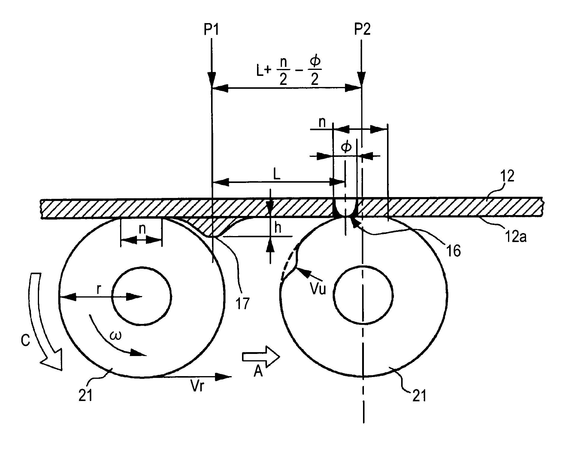
[0033] On the bottom surface of the print head 10, the nozzle member 12 including a nozzle surface 12a is arranged. The nozzle member 12 is provided with a line of ink ejection nozzles 16 arranged so that its longitudin...
second embodiment
[0053]FIG. 10 is a sectional side view of the essential part of a head cartridge according to the present invention. As shown in FIG. 10, the cleaning roller 21 is accommodated adjacent on one side within the head cap 11 provided on the bottom surface of the print head 10 of the head cartridge 3. The cleaning roller 21 is integrally provided with a rotational shaft 25 that is journaled on bearings 26 arranged on the bottom surface of the head cap 11 in its longitudinal direction.
[0054] Moreover, the rotational shaft 25 is integrally provided with an eccentric cam 27. A half of a slide-contact surface 27b of the eccentric cam 27 shown in FIG. 10 is formed to have the same rotational radius while the other half is outward protruded to have different rotational radii. The slide-contact surface 27b is brought into contact with the upper surface of a fixed part 28 provided in the bearing 26, so that the eccentric cam 27 is eccentrically rotated on the fixed part 28 so as to elevate the c...
PUM
 Abstract
Description
Claims
Application Information
 - R&D
- Intellectual Property
- Life Sciences
- Materials
- Tech Scout
- Unparalleled Data Quality
- Higher Quality Content
- 60% Fewer Hallucinations
Browse by: Latest US Patents, China's latest patents, Technical Efficacy Thesaurus, Application Domain, Technology Topic, Popular Technical Reports.
© 2025 PatSnap. All rights reserved.Legal|Privacy policy|Modern Slavery Act Transparency Statement|Sitemap|About US| Contact US: help@patsnap.com


