Phase shifting network

Inactive Publication Date: 2005-10-06
ANDREW CORP
View PDF14 Cites 40 Cited by
  • Summary
  • Abstract
  • Description
  • Claims
  • Application Information

AI Technical Summary

Benefits of technology

[0010] It is an object of the invention to provide an antenna phase shifting network for adjusting phase between antenna elements arranged as an inner pair and an outer pair, with lower bulk than prior systems. It is a further object of the invention to provide an antenna phase shifting network with phase shift adjusters of a relatively simple construction.
[0016] This arrangement provides a reduced number of differential phase shifters, compared with the arrangement of FIG. 1. It also provides an alternative power division arrangement compared with FIG. 2.
[0019] The network may have an odd number of outputs, but most preferably has only an even number of outputs. An even number of outputs is advantageous for use in an antenna with an even number of radiating elements.
[0027] In common with the first exemplary embodiment, this arrangement provides a reduced number of differential phase shifters, compared with the arrangement of FIG. 1. It also provides an alternative power division arrangement compared with FIG. 2. The even number of outputs is advantageous for use in an antenna with an even number of radiating elements.
[0028] The ratio between the first and second phase shift adjusters may fall outside the 1:3 ratio described above in connection with the first exemplary embodiment. When implemented in an antenna, this permits variation from equal spacing between adjacent radiating elements.

Problems solved by technology

A disadvantage of the prior art shifting networks is that they are unsuitable for such an antenna shape because they are bulky in the width direction “W”, perpendicular to “L”.
This problem would worsen if the number of antenna elements was increased.

Method used


Image

  • Phase shifting network
  • Phase shifting network
  • Phase shifting network

Examples


first embodiment

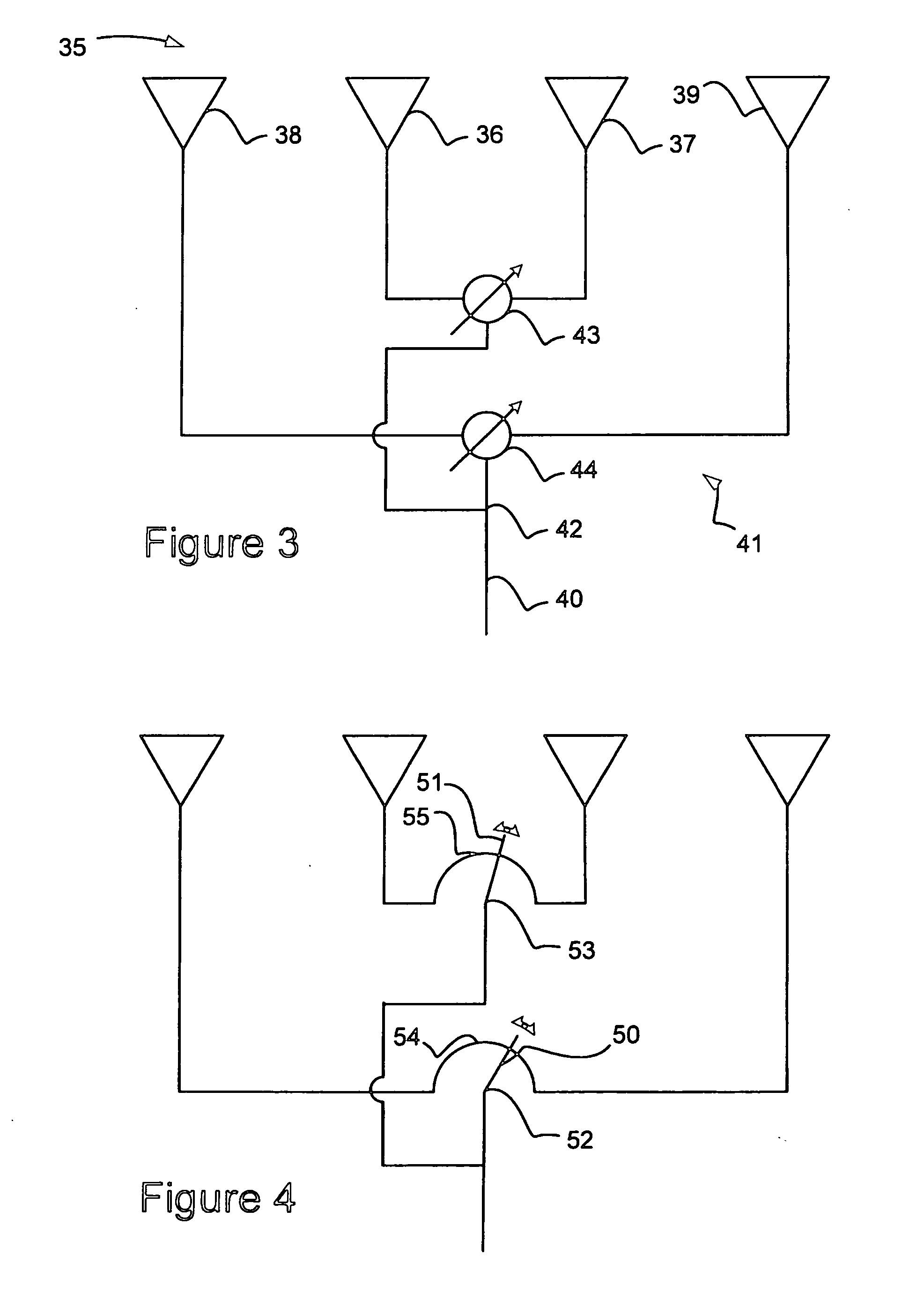
[0033]FIG. 4 is a schematic drawing of the generic network of FIG. 3;

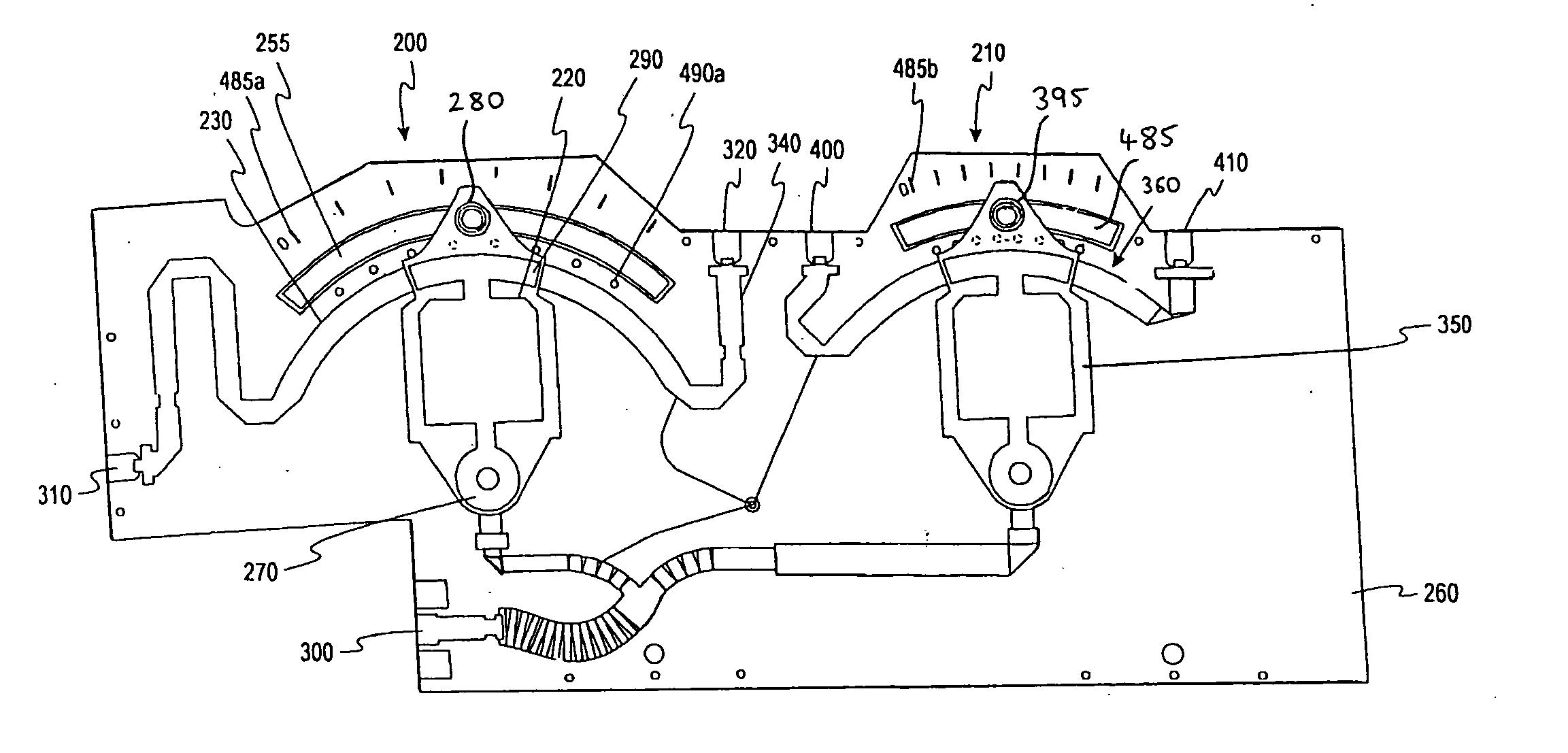
[0034]FIG. 5 is a front view of the network of FIG. 4;

[0035]FIG. 6 is a rear view of the network of FIG. 4;

second embodiment

[0036]FIG. 7 is a schematic drawing of the generic network of FIG. 3;

third embodiment

[0037]FIG. 8 is a schematic drawing of the generic network of FIG. 3;

[0038]FIG. 9 is a schematic drawing of an antenna incorporating a generic three-pair phase shifting network according to the invention;

[0039]FIG. 10 is a schematic drawing of an antenna incorporating a first generic four-pair phase shifting network; and

[0040]FIG. 11 is a schematic drawing of an antenna incorporating a second generic four-pair phase shifting network.


PUM


Abstract

A phase shifting network including a main power divider having a main input, first and second main outputs, and means for dividing power received at the main input between the first and second main outputs. A first differential phase shifter is provided. The first differential phase shifter has a first input, first and second outputs, and a first phase shift adjuster which can be moved to adjust the phase difference between the first and second outputs. The first input is connected to the first main output and the first differential phase shifter is configured to divide power from the first input between the first and second outputs. A second differential phase shifter is also provided. The second differential phase shifter has a second input, third and fourth outputs, and a second phase shift adjuster which can be moved to adjust the phase difference between the third and fourth outputs. The second input is connected to the second main output and the second differential phase shifter is configured to divide power from the second input between the third and fourth outputs. A control system is configured to drive the first phase shift adjuster and the second phase shift adjuster, such that the degree of adjustment of one of the phase shift adjusters is dependent upon the degree of adjustment of the other phase shift adjuster. The phase difference between the first and second outputs, the second and third outputs, and the first and fourth outputs is substantially equal.

Description

FIELD OF THE INVENTION [0001] The invention relates to a phase shifting network. In particular, the invention relates to a phase shifting network for feeding, and adjusting the phase between, two or more pairs of antenna elements. BACKGROUND OF THE INVENTION [0002] Phase shifting networks are used to adjust the radiation patterns of antennas. By adjusting the phase angle of individual antenna elements, it is possible to adjust properties of the antenna beam, such as down tilt and beam width. These adjustments are desirable as they make it possible to adjust the area covered by the antenna or to improve antenna performance. [0003] U.S. Pat. No. 6,198,458 describes a network which employs differential phase shifters, as shown schematically in FIG. 1. The antenna consists of four antenna elements 5, 6, 7, 8. The antenna elements are fed by an input 12 via a phase shifting network 13. The phase shifting network 13 consists of a first differential phase shifter 14 which receives the inpu...

Claims


Application Information

Patent Timeline
IPC IPC(8): H01P1/18H01Q3/00H01Q3/30
CPCH01P1/18H01Q3/30H01P1/184
Inventor ELLIOT, ROBERT DOUGLAS
Owner ANDREW CORP
Why Eureka
Try Eureka