
In-place differential compression

a differential compression and in-place technology, applied in the field of in-place differential compression, can solve the problem of not providing in-place decoding, and achieve the effect of enhancing the effectiveness of copying substrings and better aligning s

Inactive Publication Date: 2005-10-06
STORER JAMES ANDREW +1
View PDF26 Cites 37 Cited by
  • Summary
  • Abstract
  • Description
  • Claims
  • Application Information

AI Technical Summary

Benefits of technology

"The invention is about a method for compressing data by comparing it to another set of data and using a pointer to copy parts of the first data into the second data. This is done by rearranging the parts of the first data to match up with the second data. The method is called in-place differential compression because it compresses the data without overwriting the original memory. The technical effect of this invention is to provide a more efficient way to compress data by aligning it with another set of data and using a pointer to copy parts of the first data into the second data."

Problems solved by technology

Burns and Long , M. Ajtai, R. Burns, R. Fagin, and D. D. E. Long , and the U.S. patent of Ajtai, Burns, Fagin, and Stockmeyer [U.S. Pat. No. 6,374,250] use a hash table with Karp-Rabin footprints to perform differential compression of one file with respect to another, using constant space in addition to that used by both files, but do not provide for in-place decoding.
Burns and Long , Burns, Stockmeyer, and Long , and the U.S. patent of Burns and Long [U.S. Pat. No. 6,018,747] present an in-place reconstruction of differential compressed data, but do not perform the reconstruction with copies that overwrite from left to right.

Method used


Image

  • In-place differential compression
  • In-place differential compression
  • In-place differential compression

Examples


case 0

[0084] It is also possible to employ an off-the-shelf variable length coder to encode fields of a pointer. For example, to compress data where very large matches may be present, one could use the following coding method for pointers that employs an arithmetic coder: [0085] The pointer format begins with a control integer between 0 and 4 that indicates one of the following cases: [0086] No displacement or length; the bits to follow indicate a single raw character. [0087] Case 1: Displacements[0088] Case 2: Displacements between 4 KB and 36 KB that point to a match of length[0089] Case 3: Displacements larger than 36 KB that point to a match of length[0090] Case 4: Displacements larger than 36 KB that point to a match of length≧256.

[0091] Separate off-the-shelf arithmetic encoders are used to encode control integers, the raw character for Case 0, and the length fields for Cases 1 through 3.

[0092] A fixed code of either 12 or 15 bits is used for the displacements for Cases 1 and 2. ...


PUM


Abstract

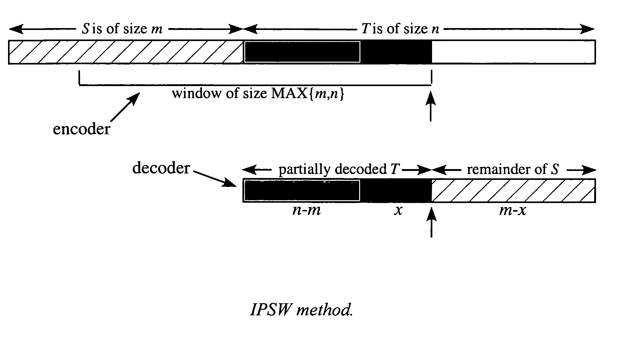
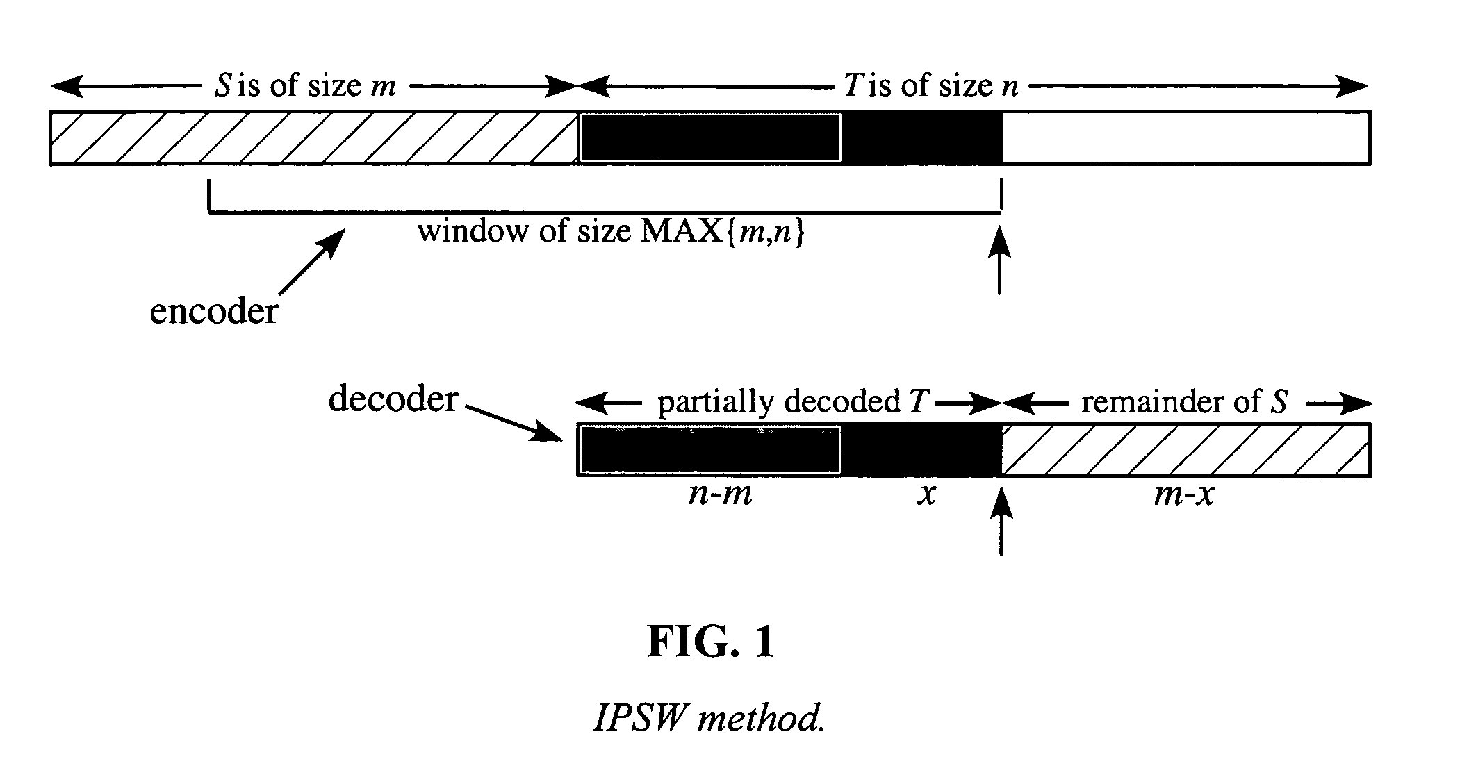
To enhance the distribution or backup of data similar to previously distributed or backed up data, to provide similarity testing, and other benefits, a first body of data T of size n is compressed with respect to a second body of data S of size m in-place; that is, the memory containing S is overwritten from left to right so that at no time is more than a total of MAX{m,n}+O(1) memory used.

Description

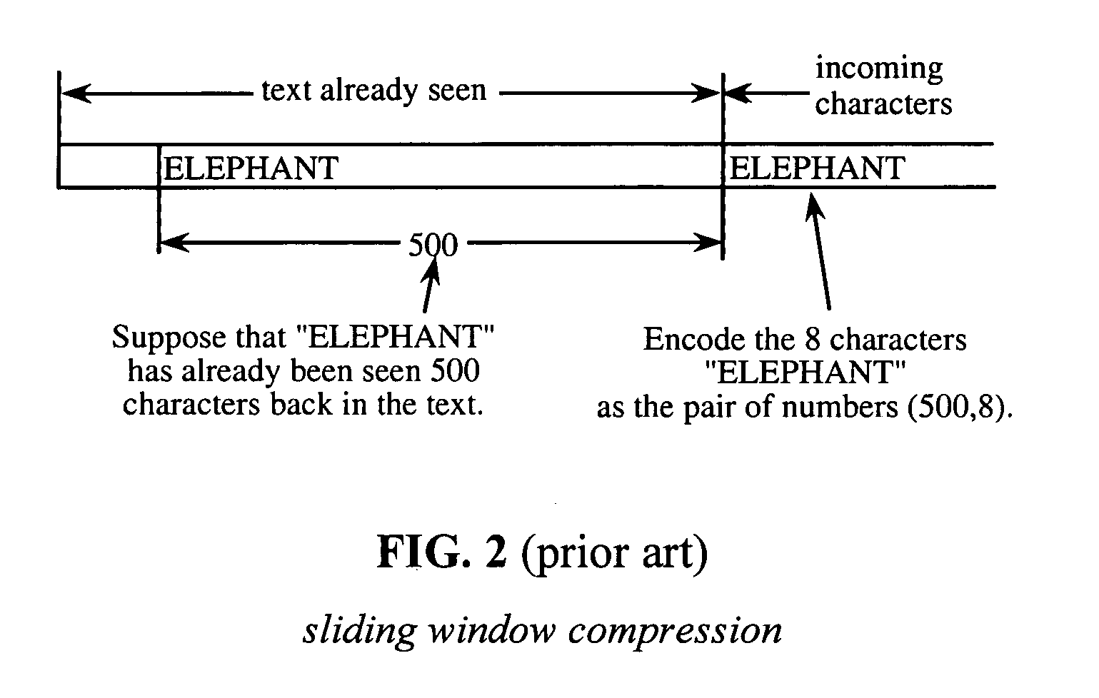
BACKGROUND OF THE INVENTION [0001] The present invention relates to in-place differential compression, where a body of data T is compressed with respect to a body of data S by performing copies from S in such a way that no additional memory is used beyond what is needed to store the longer of S or T; that is, when decoding, S is overwritten from left to right as T is constructed in its place. [0002] There have been many patents and technical papers that pertain to data compression. Many relate to techniques different than ones that employ string copying such as Huffman coding (e.g., U.S. Pat. No. 4,646,061) or arithmetic coding (e.g., U.S. Pat. No. 4,905,297). Many relate to techniques that employ string copies but in a traditional data compression model where a single body of data is compressed, not in-place differential compression of a first body of data with respect to a second body of data; for example, U.S. patents such as Holtz [U.S. Pat. No. 4,366,551], Welch [U.S. Pat. No. ...

Claims


Application Information

Patent Timeline
Patent Type & Authority Applications(United States)
IPC IPC(8): G06F11/14H03M7/30H03M7/34
CPCG06F11/1451H03M7/3086H03M7/30
Inventor STORER, JAMES ANDREWSHAPIRA, DANA
Owner STORER JAMES ANDREW
Learn More