
Magnetic resonance imaging device

a technology of magnetic resonance imaging and measuring eddy currents, which is applied in the direction of measurement devices, magnetic measurements, instruments, etc., can solve the problems of reducing the level of nmr signals for measuring eddy currents having a long time constant according to the level of nmr signals, reducing the measurement accuracy of eddy currents having a long time constant, and measuring objects

Inactive Publication Date: 2005-10-06
HITACHI LTD
View PDF4 Cites 20 Cited by
  • Summary
  • Abstract
  • Description
  • Claims
  • Application Information

AI Technical Summary

Benefits of technology

[0011] Further, the gradient magnetic field applied for a longer time than the time constant of the c

Problems solved by technology

However, since the FID signals measured with the conventional art decay according to lapse of time, a level of NMR signals for measuring an eddy current having a long time constant reduces according to time, namely, since S / N reduces according to lapse of time, it is afraid that the measurement accuracy of eddy currents having a long time constant will be reduced.
However, the measurement object in the above conventional art is limited only to the eddy current components induced at the time when the gradient magnetic field falls, and the conventional art does not disclose to measure the influence to the magnetic field due to the eddy current component induced when the gradient magnetic field rises and to compensate the same.

Method used


Image

  • Magnetic resonance imaging device
  • Magnetic resonance imaging device
  • Magnetic resonance imaging device

Examples


Embodiment Construction

[0021] Embodiments of the present invention will be explained herein below.

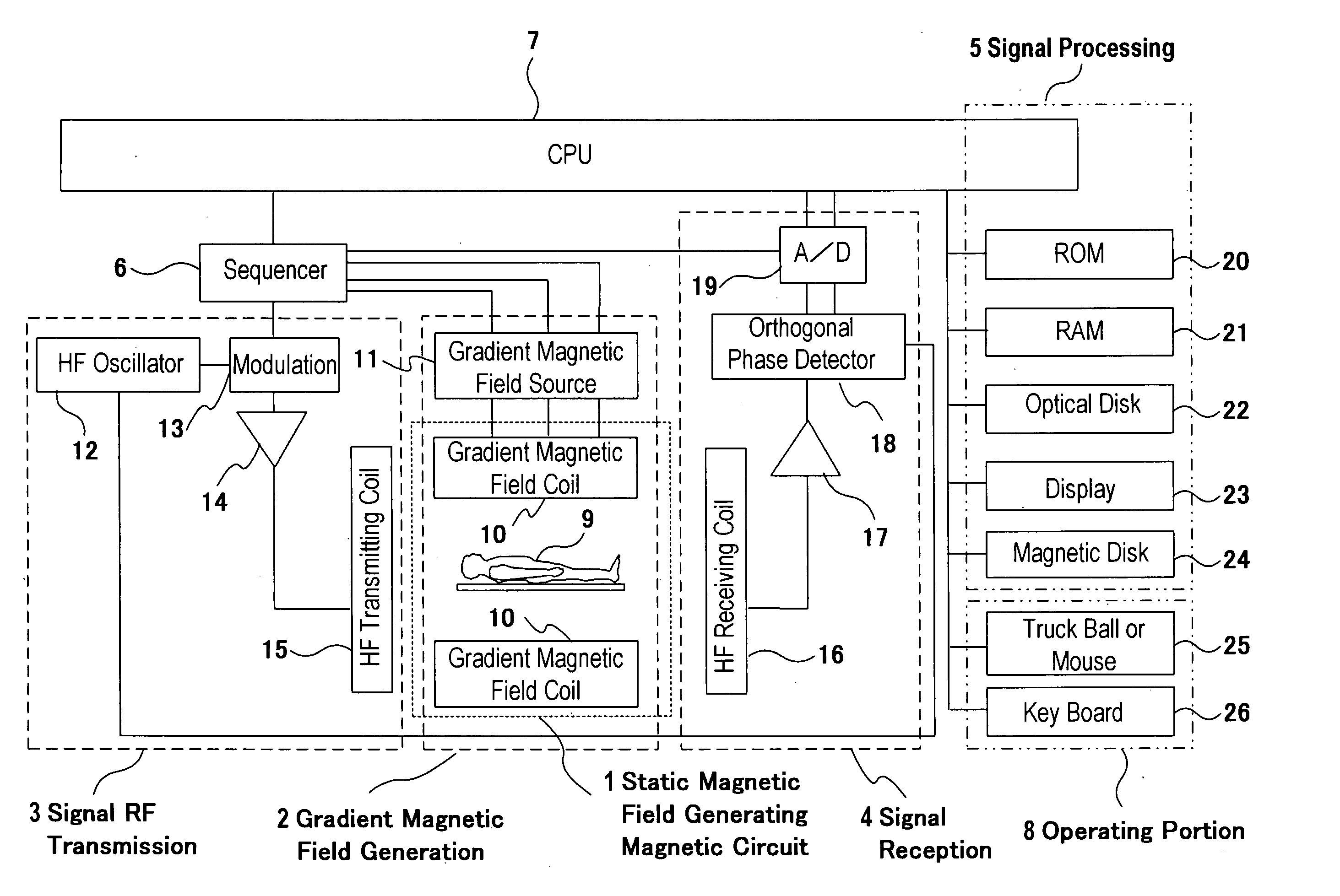
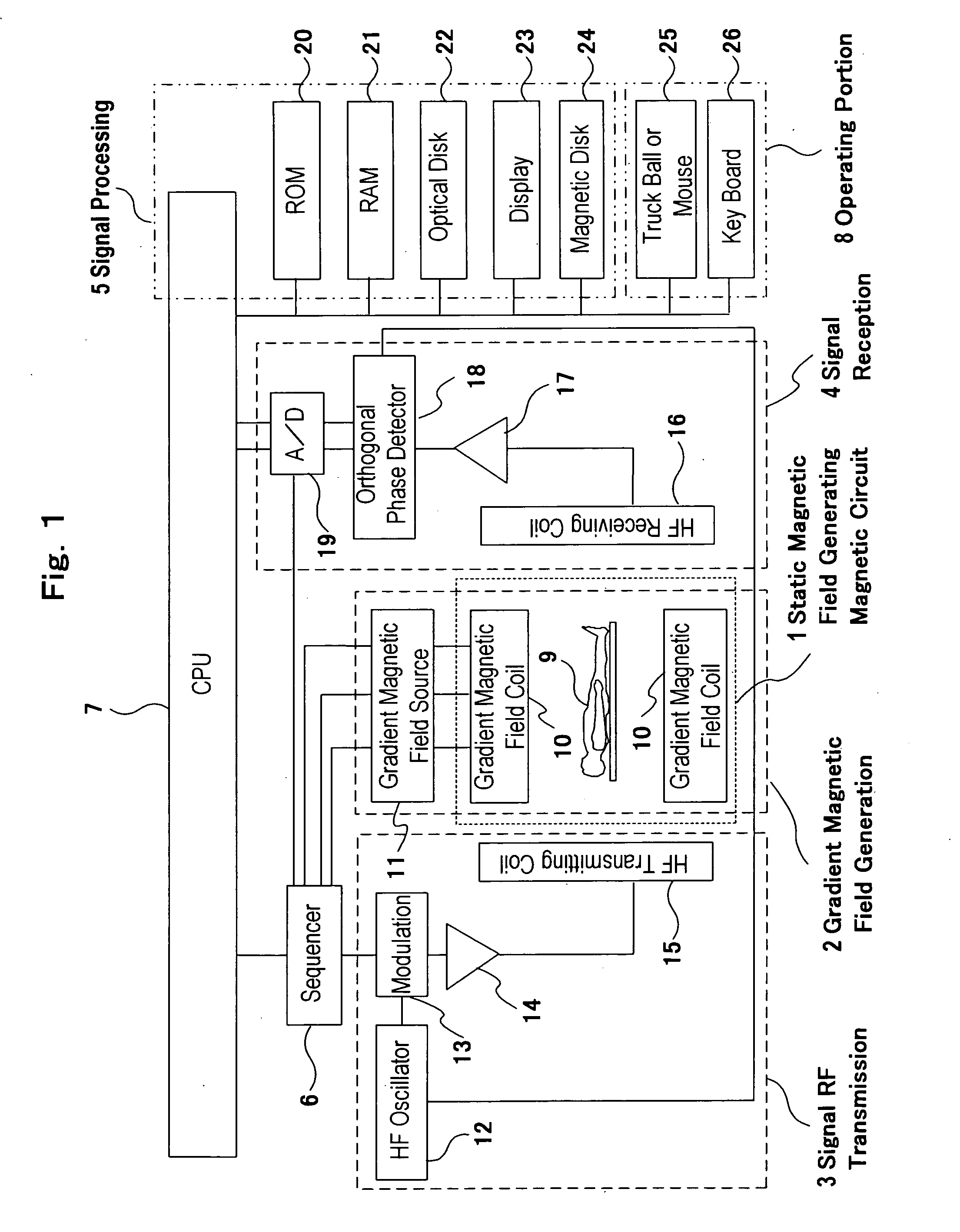
[0022]FIG. 1 is a block diagram showing an entire outline of an MRI apparatus to which the present invention is applied. The MRI apparatus comprises, as its primary constituents, a static magnetic field generating magnetic circuit 1 for generating homogeneous static magnetic field in a space where a subject 9 is placed, a gradient magnetic field generating system 2 for providing magnetic field gradient to the static magnetic field, a signal transmission system 3 for generating high frequency (RF) magnetic field which causes nuclear magnetic resonance phenomenon in atomic nuclei (usually proton) of atoms constituting tissue of the subject 9, a signal receiving system 4 for receiving echo signals generated from the tissue of the subject 9 through the nuclear magnetic resonance phenomenon, a signal processing system 5 which processes the echo signals received by the signal receiving system 4 and reconstructs an...


PUM


Abstract

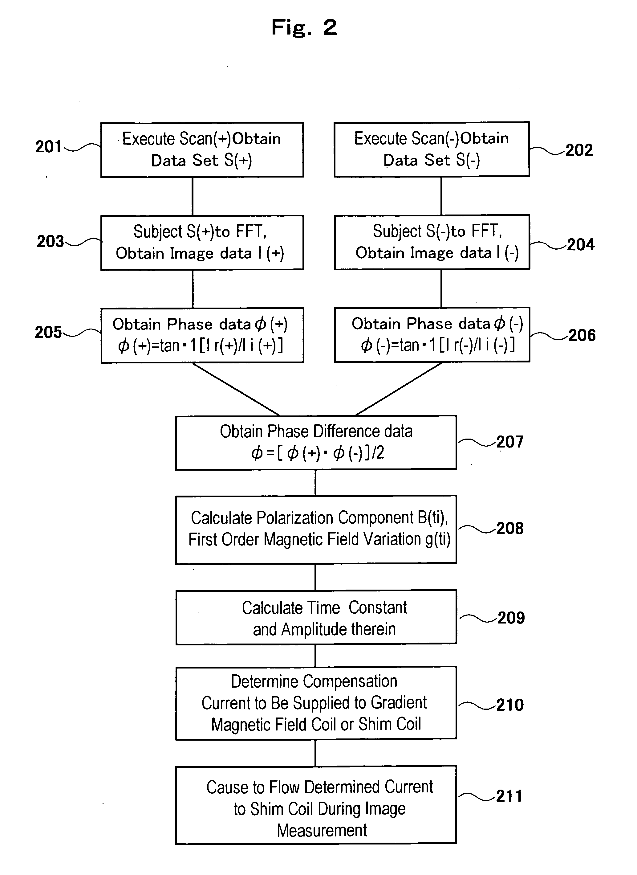
An MRI apparatus having a calibration pulse sequence, wherein a group of pulse sequences for applying test gradient magnetic fields are established from a basic pulse sequence by a gradient echo method of short TR, a group of pulse sequences not applying test gradient fields are established from the basic pulse sequence, a set of three- or four-dimensional data including a time variable is created by using echo signals collected by at least one of the groups, two data sets are created as a whole by inverting the polarity of the test gradient magnetic field, the difference between phase images thereof is determined, the magnitude and time constant of eddy current induced at the fall or rise of the gradient magnetic field are determined from the phase difference image, and the variation of the magnetic field due to eddy current induced at the rise and / or fall of the gradient magnetic field can be measured in a relatively short time with a desired time resolution even if the magnetic field variation is of a very long time constant.

Description

FIELD OF THE INVENTION [0001] The present invention relates to a magnetic resonance imaging apparatus (hereinafter will be called as MRI apparatus) which makes use of nuclear magnetic resonance phenomenon and permits to obtain a tomographic image of any desired positions of a subject and in particular, relates to a technology for preventing an image quality deterioration such as image distortion, signal intensity reduction and ghosting which is caused by a gradient magnetic field waveform distortion due to eddy current induced by an application of gradient magnetic field. BACKGROUND ART [0002] An MRI apparatus causes atomic nuclear (usually proton) existing in any desired regions of a subject nuclear magnetic resonance phenomenon through application of high frequency magnetic field on to the subject placed in homogeneous static magnetic field and obtains a tomographic image of the region from nuclear magnetic resonance signals (echo signals) induced thereby. In this instance, in ord...

Claims


Application Information

Patent Timeline
IPC IPC(8): G01R33/565
CPCG01R33/56518
Inventor MIYAWAKI, SHOUICHITAKEUCHI, HIROYUKIKUMAI, HIDEKI
Owner HITACHI LTD
Learn More