
Method and a device for depositing a wipe-proof and rub-proof marking onto transparent glass

a technology of transparent glass and markings, applied in the field of two-dimensional codes, can solve the problems of insufficient possibilities, no unique serial number of these technologies, and the lack of labeling, and achieve the effect of not damage to the glass

Inactive Publication Date: 2005-10-06
FREWITT PRINTING
View PDF21 Cites 36 Cited by
  • Summary
  • Abstract
  • Description
  • Claims
  • Application Information

AI Technical Summary

Benefits of technology

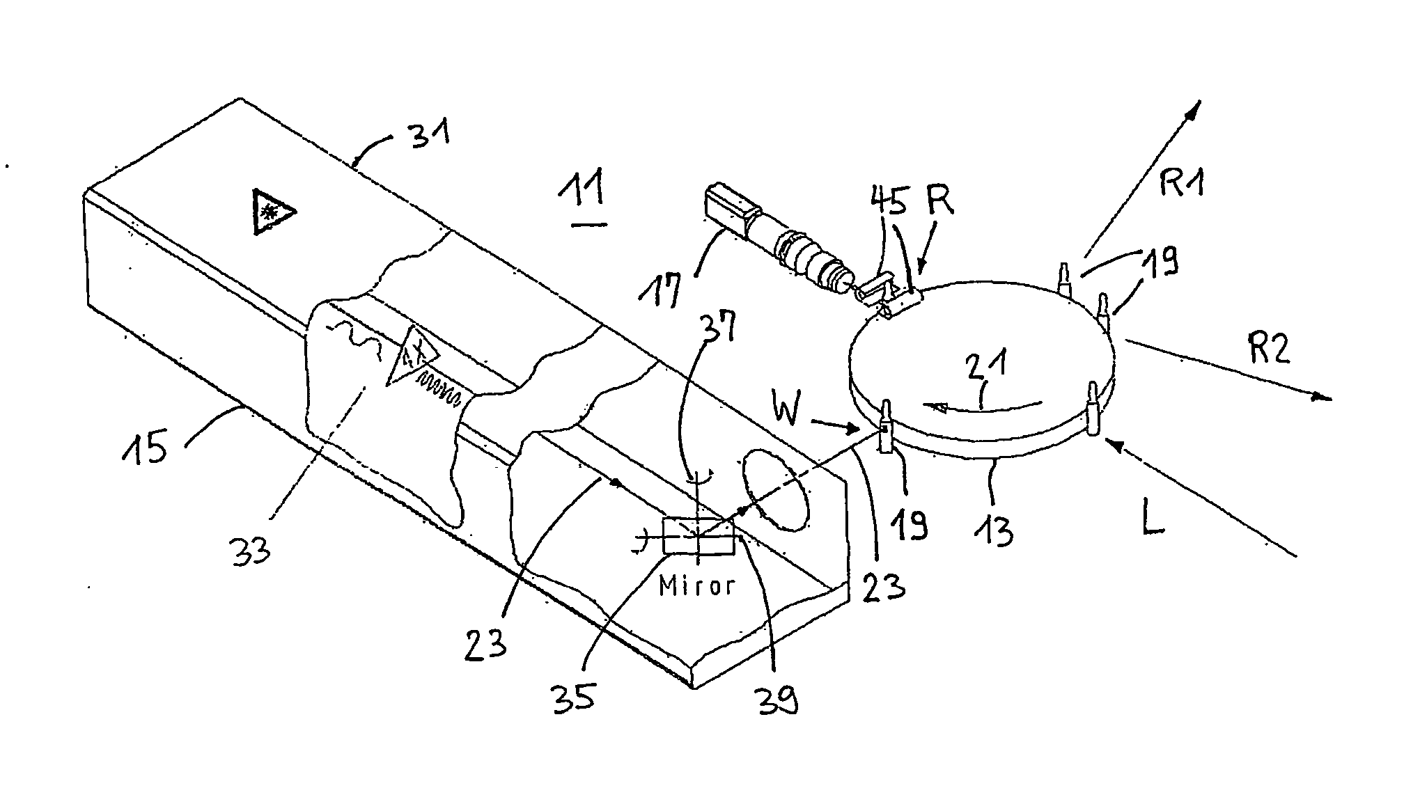
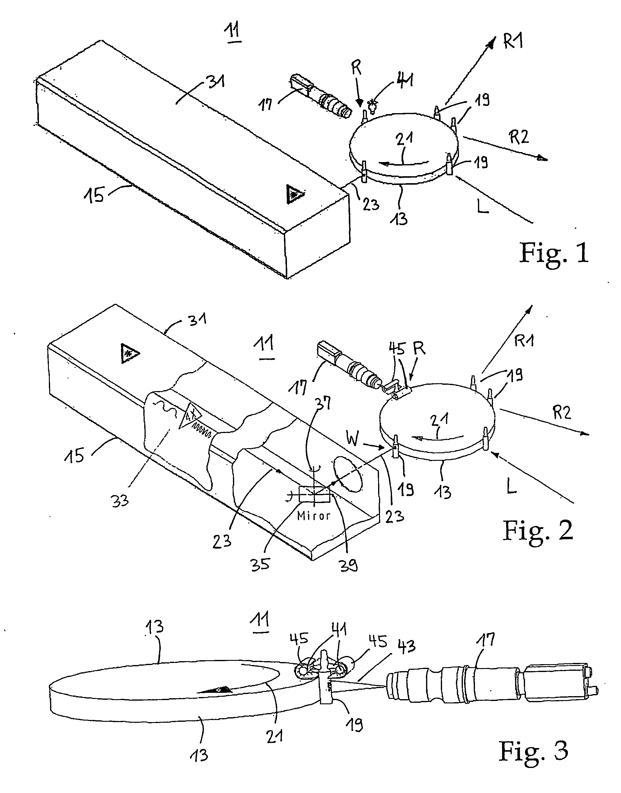
[0022] It is the object of the present invention to suggest a method and a device for the direct and unambiguous distinguishing of preferably transparent glass receptacles without the application of masks. A further object is to suggest a method and a device in order to engrave a wipe-proof marking or inscription into the surfaces of glass ampoules, syringes, small glasses and likewise, in particular a machine-readable two-dimensional point or line code (datamatrix). It is further an object to suggest a method and a device with which markings may be written onto moved glass objects (“on the fly”). A further object is to suggest a method and a device or a system with which a rub-free marking or code marking may be written into curved surfaces, in particular into surface areas of round glass receptacles. It is yet a further object to deposit rub-proof and non-manipulatable markings onto transparent glass without the use of masks or additional coatings and without damage to the glass. A further object is to suggest a complete solution for the manufacture of rub-proof, individual markings of pharmaceutical receptacles which may be integrated into existing filling installations and which in particular meets the requirements of the pharmaceutical industry. DESCRIPTION OF THE INVENTION

Problems solved by technology

The disadvantage with labelling by way of writing inks is however the fact that the labelling is usually not wipe-proof and / or rub-proof.
The limited number of rings and the different colours however do not permit each individual sample to be individualised which would be desirable, but as a rule only permits details with regard to the batch in the manufacturing process.
None of these technologies allow a unique serial number (not enough possibilities)
This however entails considerably more expense since the code marking until now had to be deposited onto the am ampoules pull a by the manufacturer of the ampoules.
This is complicated and makes the filling procedure considerably more expensive.
Attempts by the inventor have however shown that with point coding used in practice nowadays it is practically impossible to form a point of the point matrix as a diffusely scattering reflector, similar to a cat's eye.
This is impossible already due to the fact that an individual point occupies an area of significantly less than 1 mm2.
The use of a CCD camera failed due to the fact that the contrast between the written and bordering area is not sufficient to be able to reliably read the point pattern.
On the other hand the disadvantages of the method and the device of DE-A-100 50 263 are that the object to be inscribed must be moved perpendicularly to the tangential plane in the apex of the surface in dependence on the curvature of the surface to be inscribed.
Due to the necessary complicated handling the inscription method is not suitable for inscribing a very large number of objects in a certain time unit, as this is required in the pharmaceutical industry.
This is not least due to the fact that until now there have not been available any suitable or satisfactory alternative solutions.
With regard to this one had reservations with respect to laser inscription since the glass may be damaged at the irradiated locations (cracks).

Method used


Image

  • Method and a device for depositing a wipe-proof and rub-proof marking onto transparent glass
  • Method and a device for depositing a wipe-proof and rub-proof marking onto transparent glass
  • Method and a device for depositing a wipe-proof and rub-proof marking onto transparent glass

Examples


Embodiment Construction

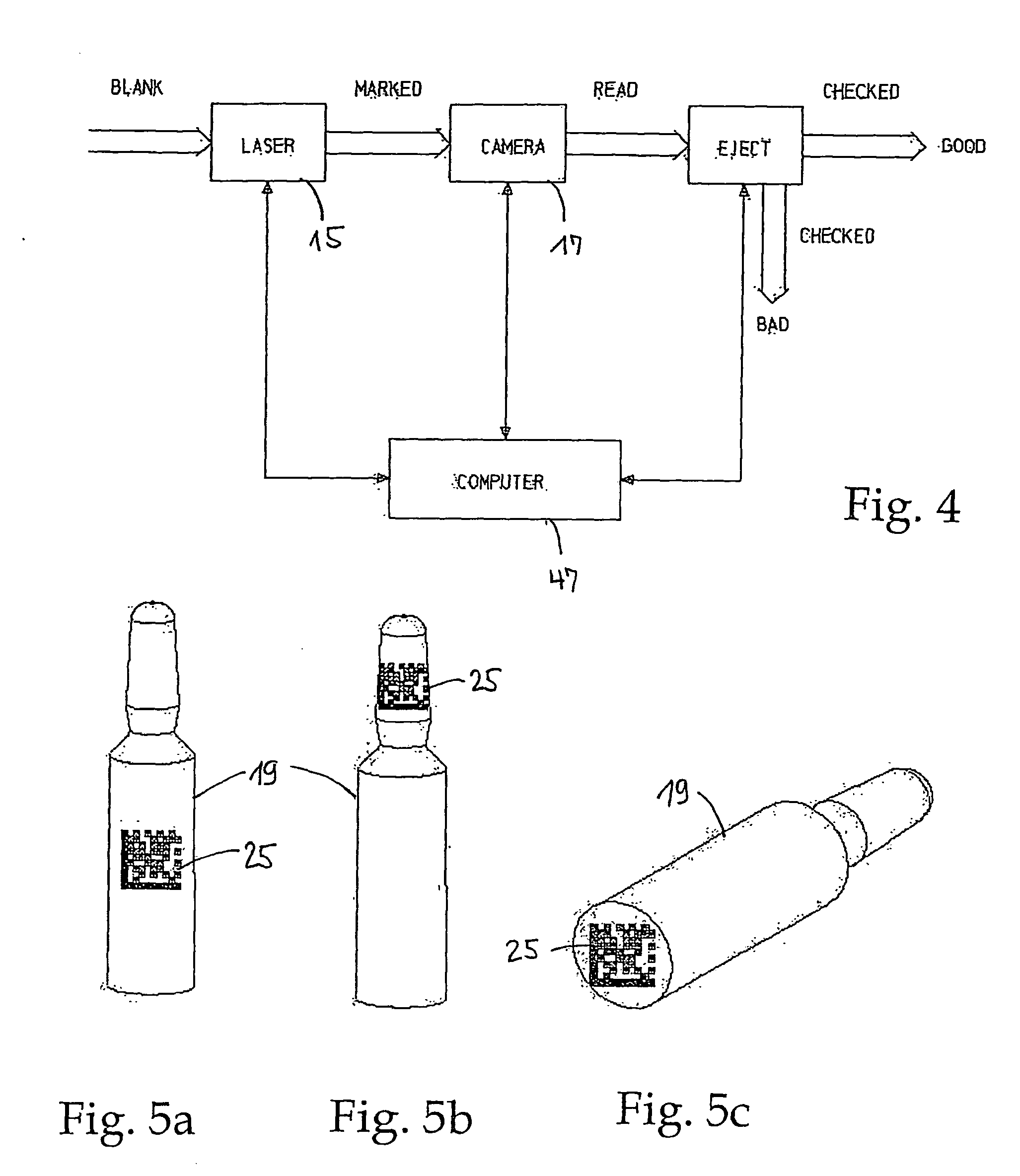
[0023] According to the invention this object is achieved by a method with the features of claim 1. By way of a transport means a large number of glass receptacles may be transported past a laser. By way of detecting the position of a glass receptacle and as the case may be the transport speed of the transport means the laser beam may be triggered at the right moment and a marking pattern stored in a memory medium engraved into the surface. The marking engraved into the surface may be scanned and detected directly after the writing procedure by way of a suitable read means and may be compared to the marking pattern stored in the memory medium. By way of a comparison of the predefined code pattern with the actually written code pattern one may ascertain immediately whether the inscription is OK. One may thus meet the demand of a hundred percent retracability of the samples. Thus a mixing up of medications may no longer occur on account of a marking engraved into the glass surface. Th...


PUM

PropertyMeasurementUnit
Radiusaaaaaaaaaa
Radiusaaaaaaaaaa
Radiusaaaaaaaaaa

Abstract

A device for depositing a wipe-proof and rub-proof marking or code marking, in particular a two-dimensional matrix or line coding onto glass receptacles such as glass ampoules, glass bottles, vials and likewise, comprises a transport means having a drive, with one or more accommodating devices for objects to be inscribed, a laser system arranged at a distance to the transport means with a laser source for producing a laser light beam of a wavelength <380 nm, said laser light beam in operation being directed onto the transport path and defining an impingement point in the region of at least one accommodating means moved along the transport path, means in order to deflect the laser light beam in a first and in a second direction continuously or in certain incremental intervals, and at least one control unit comprising a memory unit and a microprocessor which is in connection with the laser system and the deflection means, for controlling at least the deflection system and the laser system. The device further comprises a transport means designed for the transport of glass receptacles to be marked, along a transport path, a means for detecting or determining at least the position of at least one accommodating means or a glass receptacle accommodated therein at least one position along the transport path, said means being in connection with the control unit, and a program stored in the memory unit, which triggers the laser in dependence on the position of the glass receptacle to be inscribed, as well as at least one marking pattern, according to which the deflection means for writing the 2D marking is moved in a first and in a second direction. A read means is provided or arranged at a defined read position along the transport path after the laser system in the transport direction, for detecting the marking previously written by the laser system, said read means being in connection with the control unit. In the control unit there is further present a program or a program procedure which compares the stored marking pattern to the marking detected by the read means and provides a control signal in dependence on the result of the comparison, at the output of the control unit.

Description

TECHNICAL FIELD OF THE INVENTION [0001] The present invention relates to a method and to a device for depositing a wipe-proof and rub-proof marking or code marking, in particular a two-dimensional code marking, onto glass or glass containers such as syringes, ampoules, vials, bottles and likewise. STATE OF THE ART [0002] In the pharmaceutical industry it is compellingly necessary to provide medication with a marking (subsequently also called code or code marking) in order to be able to trace back the path of these medications. The code distinguishing the pharmaceuticals should at least provide details as to when and in which manufacturing process a medication has been manufactured. It is however desirable to mark the medications with an individual code. An individual code permits the path of each individual medication to be traced (lot number and expiration date, mandatory). [0003] There are various standardised codings which are used in practise. Bar codes on printed packagings wit...

Claims


Application Information

Patent Timeline
IPC IPC(8): C03C23/00
CPCG06K1/12C03C23/0025B41M5/24B41M5/262
Inventor LEYVRAZ, PHILIPPE
Owner FREWITT PRINTING
Learn More