Bicycle crank arm

a crank arm and bicycle technology, applied in the field of bicycle cranks, can solve the problems of limited thickness of hollow parts, difficult to obtain additional weight saving using this conventional forging technique, and production cost, and achieve the effect of high rigidity

Inactive Publication Date: 2005-10-06
SHIMANO INC
View PDF21 Cites 29 Cited by
  • Summary
  • Abstract
  • Description
  • Claims
  • Application Information

AI Technical Summary

Benefits of technology

[0013] One object of the present invention is to provide a bicycle crank which is lightweight, strong and highly rigid.

Problems solved by technology

As described above, a conventional production method for crank arms is to make a hollow crank body for weight saving, requires many steps, and they are reflected in the production cost.
In addition, since it is created from a steel bar by forging, the thickness of the hollow part is limited to be approximately 4 mm even at the thinnest point.
Since all parts of the crank arm are made as thin as possible with this conventional forging technique, additional weight saving is difficult to obtain using this conventional forging technique.
Materials are also limited to aluminum alloy because it is needed to form a complex shape by forging a hollow space.

Method used


Image

  • Bicycle crank arm
  • Bicycle crank arm
  • Bicycle crank arm

Examples


Embodiment Construction

[0034] Selected embodiments of the present invention will now be explained with reference to the drawings. It will be apparent to those skilled in the art from this disclosure that the following descriptions of the embodiments of the present invention are provided for illustration only and not for the purpose of limiting the invention as defined by the appended claims and their equivalents.

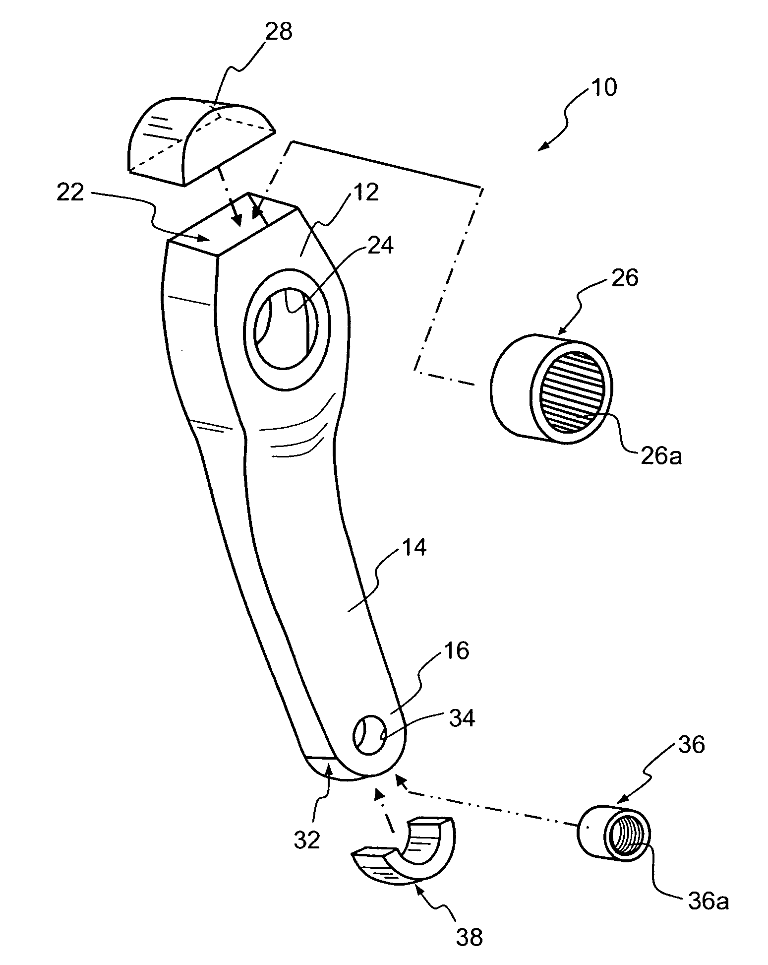
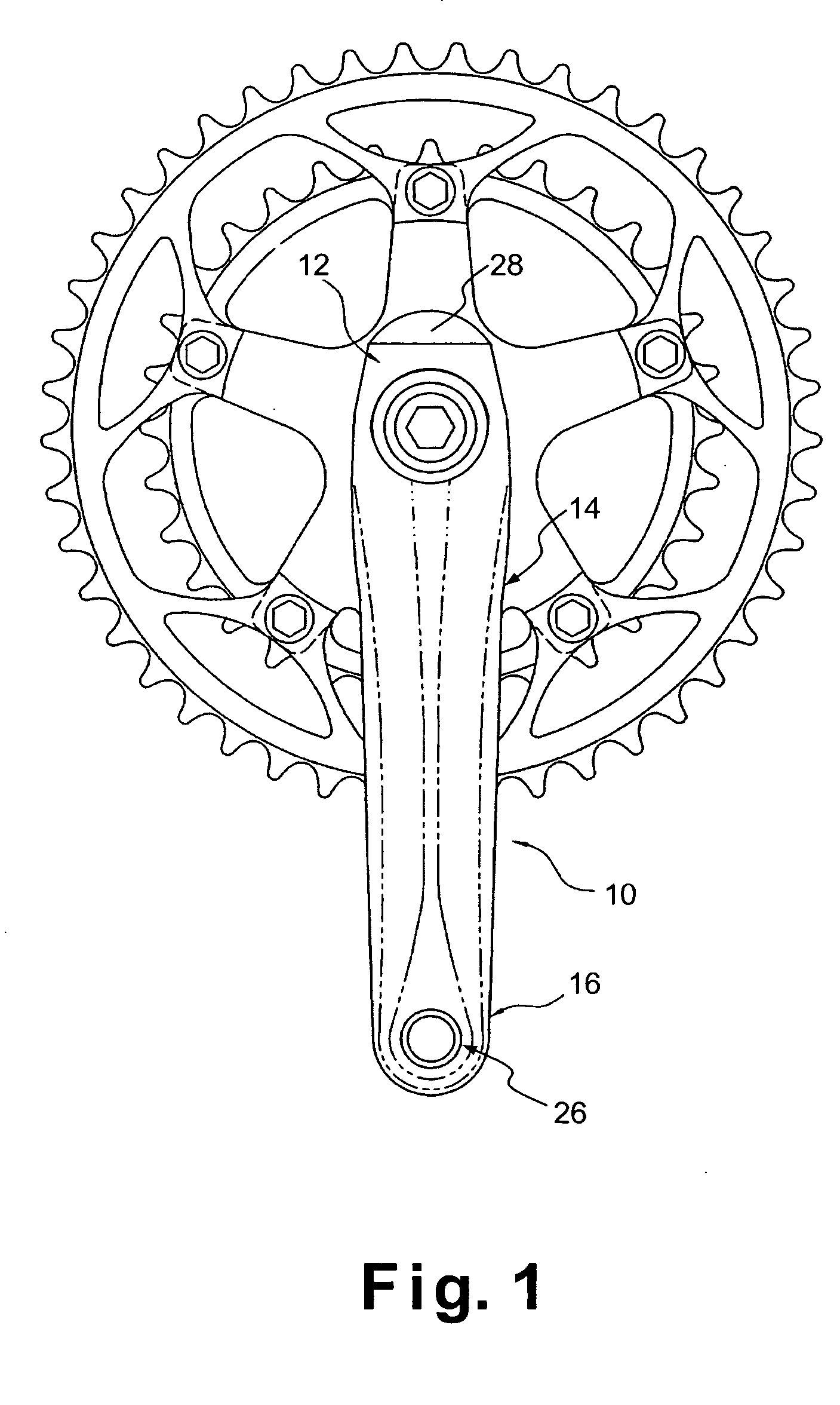
[0035] Referring initially to FIGS. 1-3, a bicycle crank set is illustrated that uses a hollow bicycle crank arm 10 in accordance with a preferred embodiment of the present invention. Basically, the hollow bicycle crank arm 10 includes a first crank axle mounting end portion 12, a central crank body portion 14 and a second pedal mounting end portion 16. The hollow bicycle crank arm 10 is preferably a one-piece, unitary member that is produced by the tube hydroforming method described below. By using the tube hydroforming method described below, the hollow bicycle crank arm 10 can be highly design...


PUM


Abstract

A bicycle crank arm is provided that is a light, highly strong, highly rigid and highly designed in a complex shape. The bicycle crank arm has a crank axle mounting end portion, a central crank body portion and a pedal mounting end portion. The hollow bicycle crank arm is preferably a one-piece, unitary member that is produced by a tube hydroforming method. The hollow bicycle crank arm has a crank axle attachment part located within the crank axle mounting end portion and a pedal spindle attachment part located within the pedal mounting end portion. The mounting end portions have a crank axle hole and a pedal spindle hole, respectively, with outside diameters that are smaller than the attachment parts, respectively.

Description

CROSS-REFERENCE TO RELATED APPLICATIONS [0001] This application claims priority to Japanese Patent Application No. 2004-105277. The entire disclosure of Japanese Patent Application No. 2004-105277 is hereby incorporated herein by reference. BACKGROUND OF THE INVENTION [0002] 1. Field of the Invention [0003] The present invention generally relates to a bicycle crank and a method of producing a bicycle crank. More specifically, the present invention relates to a bicycle crank arm produced by hydroforming. [0004] 2. Background Information [0005] Bicycling is becoming an increasingly more popular form of recreation as well as a means of transportation. Moreover, bicycling has also become a very popular competitive sport. Whether the bicycle is used for recreation, transportation or competition, the current trend is to construct bicycles which are stronger as well as lighter than prior bicycles. In other words, in pursuit of faster running speed, it is desirable to reduce the weight for ...

Claims


Application Information

Patent Timeline
Patent Type & Authority Applications(United States)
IPC IPC(8): B62M3/00
CPCB21D53/86Y10T74/2164B62M3/00
Inventor UCHIDA, MITSUTOSHIHARA, MASAAKIIWAI, TORU
Owner SHIMANO INC
Why Eureka
Try Eureka