Retractable treatment instrument for endoscope
- Summary
- Abstract
- Description
- Claims
- Application Information
AI Technical Summary
Benefits of technology
Problems solved by technology
Method used
Image
Examples
first embodiment
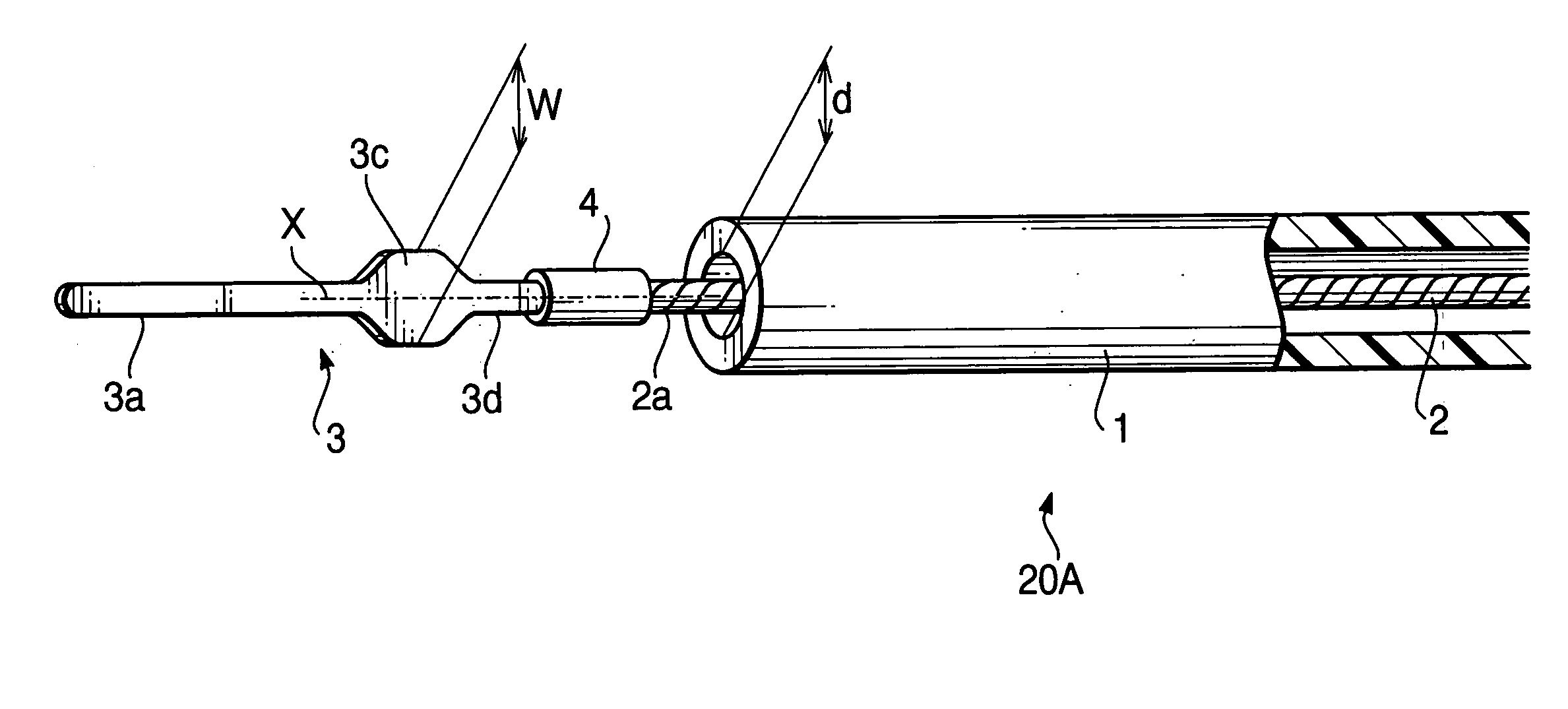
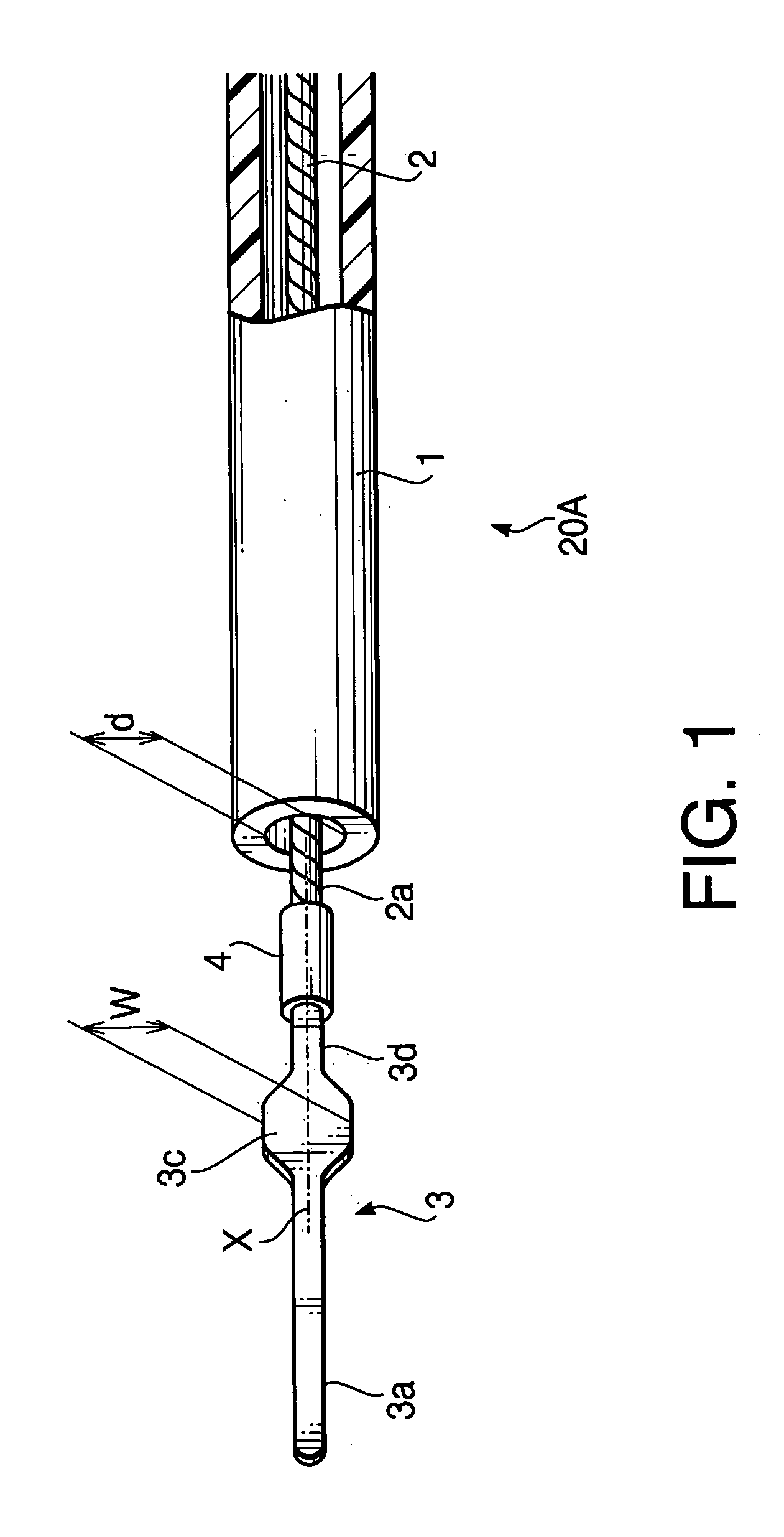
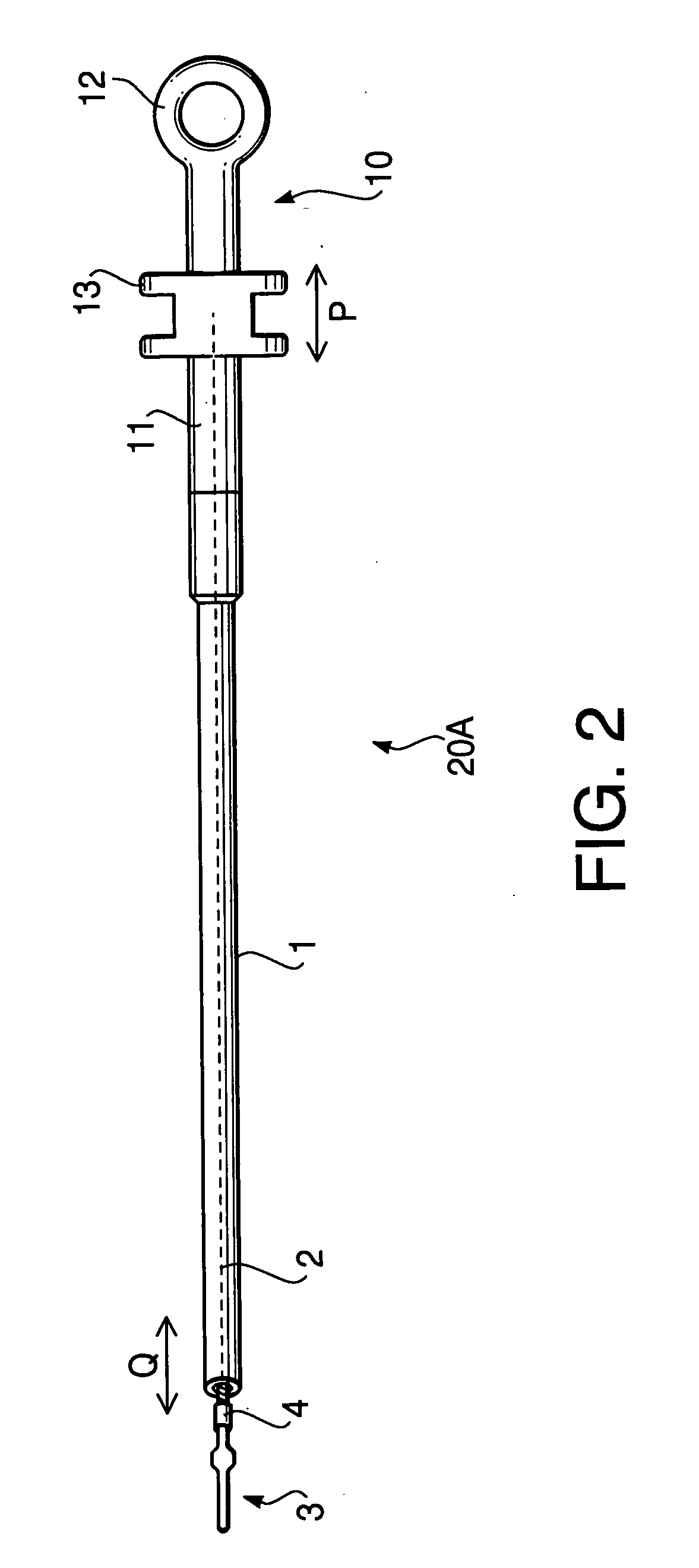
[0056]FIG. 2 is a general view of a retractable treatment instrument 20A for endoscopes according to a first embodiment of the invention. The retractable treatment instrument 20A includes a flexible sheath 1 formed of an insulative flexible tube such as a tetrafluoroethylene resin tube. A conductive operation wire 2 is disposed in the inside of the flexible sheath 1 along the length of the flexible sheath 1 so that the operation wire 2 is movable along an axial direction of the operation wire 2. The flexible sheath 1 may be configured such that at least a tip portion thereof is formed of a flexible tube.
[0057] A front-end treatment member 3 (for example, formed of a stainless steel plate) is connected to a tip of the operation wire 2 via a connection pipe 4 (for example, formed of a stainless steel pipe) so that the front-end treatment member 3 is retractable with respect to the tip of the flexible sheath 1. That is, the front-end treatment member 3 moves forward or backward with r...
second embodiment
[0069]FIG. 7 is an enlarged view of a tip portion of a retractable treatment instrument 20B for endoscopes according to a second embodiment of the invention. FIG. 8 is a general view of the retractable treatment instrument 20B according to the second embodiment. In FIGS. 7 and 8 (and in the other drawings of the second embodiment), to elements which are similar to those of the first embodiment, the same reference numbers are assigned, and the detailed description thereof will not be repeated.
[0070] One of the features of the retractable treatment instrument 20B according to the second embodiment is that a paddle 3b is formed at a tip of the rod-like part 3a of the front-end treatment member 3. The paddle 3b is configured to have a width W1 which is substantially equal to the width W of the wide part 3c or smaller than the width W to some extent.
[0071] As shown in FIG. 8, a connector 14 to which a high-frequency power source cable can be connected is located on the movable hook 13 ...
third embodiment
[0081]FIG. 17 is an enlarged view of a tip portion of a retractable treatment instrument 20C for endoscopes according to a third embodiment of the invention. FIG. 18 is a general view of the retractable treatment instrument 20C according to the third embodiment. In FIGS. 17 and 18 (and in the other drawings of the third embodiment), to elements which are similar to those of the first and second embodiments, the same reference numbers are assigned, and the detailed description thereof will not be repeated.
[0082] Similarly to the second embodiment, the retractable treatment instrument 20C is provided with the connector 14 to which a high-frequency power source cable is connected. Therefore, the retractable treatment instrument 20C is used as a high-frequency incision instrument. If the retractable treatment instrument 20C is used as a mechanical incision instrument, it is not necessary to connect the high-frequency power source cable to the connector 14.
[0083] If the operation wire ...
PUM
 Abstract
Description
Claims
Application Information
 - R&D
- Intellectual Property
- Life Sciences
- Materials
- Tech Scout
- Unparalleled Data Quality
- Higher Quality Content
- 60% Fewer Hallucinations
Browse by: Latest US Patents, China's latest patents, Technical Efficacy Thesaurus, Application Domain, Technology Topic, Popular Technical Reports.
© 2025 PatSnap. All rights reserved.Legal|Privacy policy|Modern Slavery Act Transparency Statement|Sitemap|About US| Contact US: help@patsnap.com


