
Video signal processing system video-signal processing apparatus and method, recording medium, and program

Inactive Publication Date: 2005-09-29
SONY CORP
View PDF5 Cites 16 Cited by
  • Summary
  • Abstract
  • Description
  • Claims
  • Application Information

AI Technical Summary

Benefits of technology

[0017] An object of the present invention is to immediately recover from an undecryptable state caused by loss of synchronization while encrypting / decrypting a video signal.

Problems solved by technology

By performing the digital (D) / analog (A) conversion and the A / D conversion, unfavorable signal deterioration occurs.
However, if noise is mixed into a vertical synchronizing signal or if a dropout of the vertical synchronizing signal is caused, a once-stored random number sequence serving as a frame-key value goes out of synchronization.
Accordingly, distortion of the displayed picture caused by a decryption error continues for a long time.
If encryption and decryption errors are added thereto, the pictureless-and-silent state or a picture of encrypted random numbers (picture of a noise signal) continues for four seconds at the maximum, which is undesired.
In this case, too, the “mixed-mode broadcasting” cannot be displayed if decryption of encrypted data delays.
Likewise, when a wall-hung television set is adopted, a cable used for digital connection needs to have a length of about 5 m. In this case, if an undesired noise component is mixed into a vertical synchronizing signal due to a momentary external noise, such as ESD, or if poor contact is caused at a cable connector portion, an undesired state where encrypted data cannot be decrypted continues for about two seconds.

Method used


Image

  • Video signal processing system video-signal processing apparatus and method, recording medium, and program
  • Video signal processing system video-signal processing apparatus and method, recording medium, and program
  • Video signal processing system video-signal processing apparatus and method, recording medium, and program

Examples


Embodiment Construction

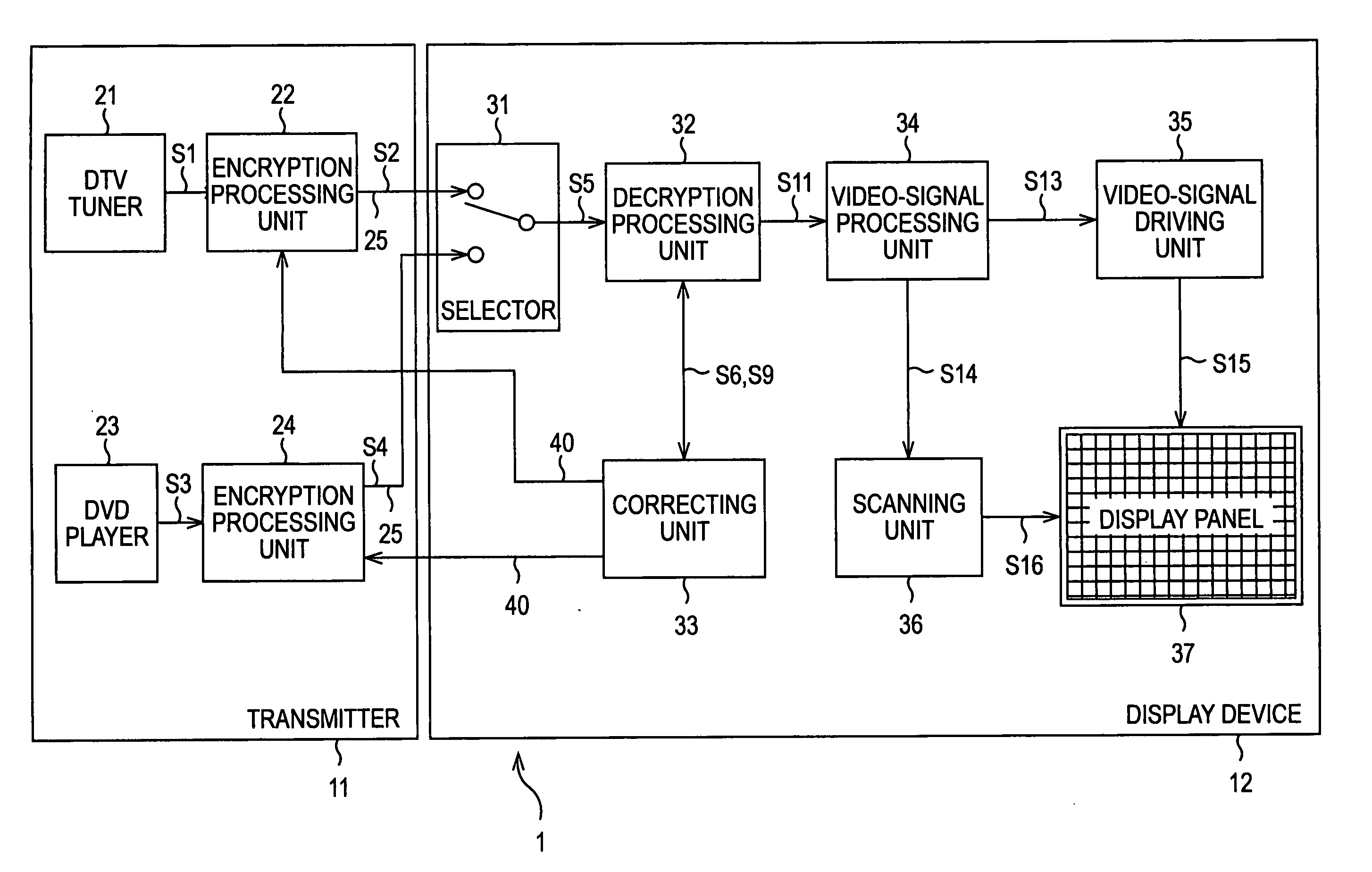
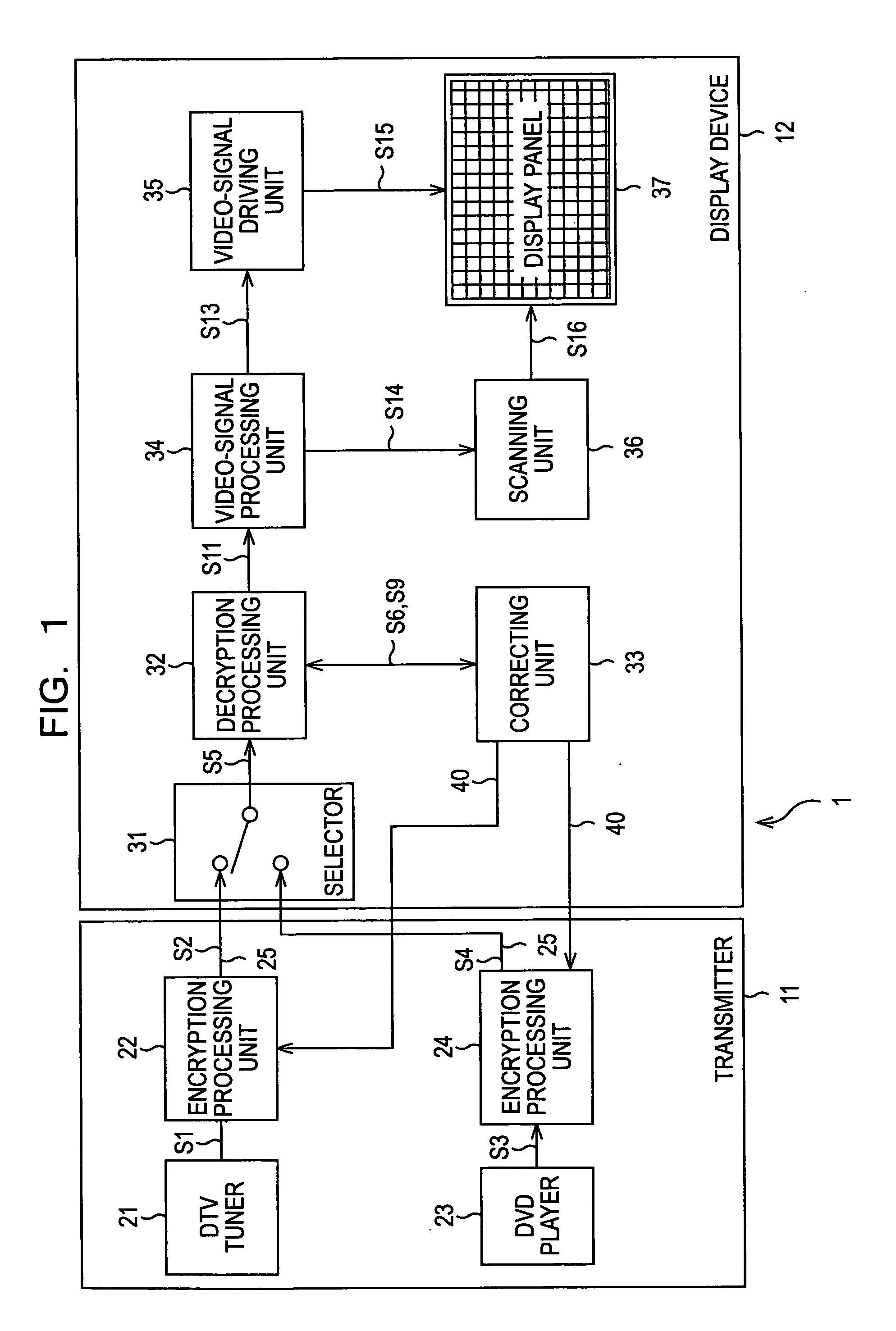
[0053]FIG. 1 shows an example of the configuration of a video-signal processing system 1, to which the present invention is applied.

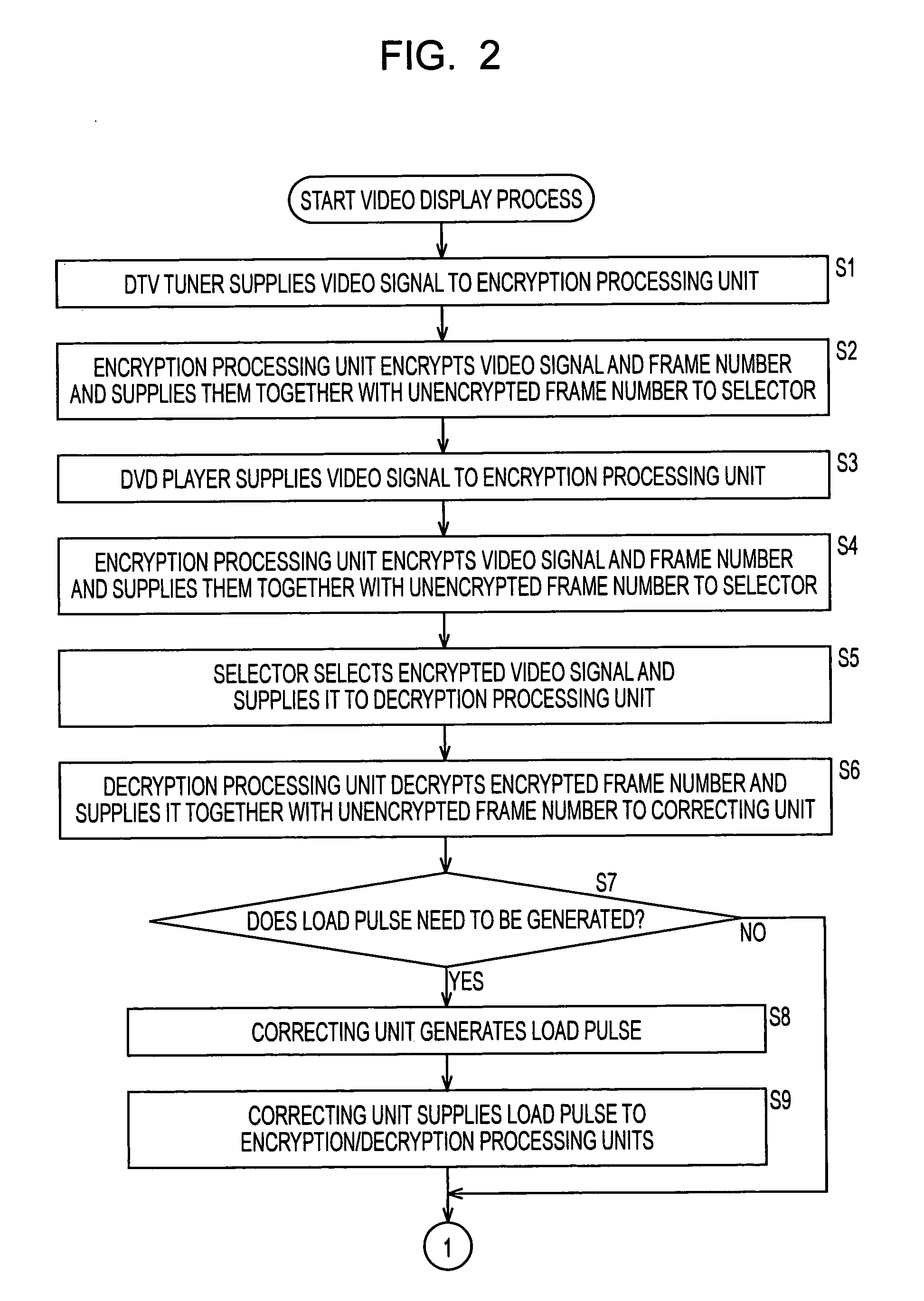
[0054] In this configuration, a wall-hung display device, such as a liquid crystal display or a plasma display panel (PDP), is used, for example. A transmitter 11 (transmitter side) includes a digital television (DTV) tuner 21, an encryption processing unit 22, a digital versatile disc (DVD) player 23, and an encryption processing unit 24. A display device 12 (receiver side) includes a selector 31, a decryption processing unit 32, a correcting unit 33, a video-signal processing unit 34, a video-signal driving unit 35, a scanning unit 36, and a display panel 37. In the figure, characters representing steps correspond to the steps in the flowchart shown in FIGS. 2 and 3, which will be described later.

[0055] The DTV tuner 21 receives a digital broadcast signal of the MPEG 2 standard, which has been received by an antenna (not shown), and demodulates the ...


PUM


Abstract

The present invention relates to a video-signal processing system, a video-signal processing apparatus and method, a recording medium, and a program for immediately recovering from loss of synchronization while encrypting / decrypting a video signal. An encryption processing unit 22 encrypts a frame number Tx, which has been obtained by counting vertical control pulses of a video signal, and transmits the frame number Tx together with an unencrypted frame number Tx and an H / V control pulse. A decryption processing unit 32 decrypts the encrypted frame number Tx so as to generate a frame number Rx and supplies the frame number Rx together with the frame number Tx and the vertical control pulses to a correcting unit 33. The correcting unit 33 generates a pseudo load pulse when the frame numbers Tx and Rx do not match with each other 16 consecutive times, and supplies the pseudo load pulse to the encryption processing unit 22 and the decryption processing unit 32. The present invention can be applied to a display device compatible with digital television.

Description

TECHNICAL FIELD [0001] The present invention relates to a video-signal processing system, a video-signal processing apparatus and method, a recording medium, and a program. In particular, the present invention relates to a video-signal processing system, a video-signal processing apparatus and method, a recording medium, and a program for recovering more immediately from a state where an encrypted video signal cannot be decrypted due to loss of synchronization. BACKGROUND ART [0002] In recent years, large and thin television receivers and back-projection projectors have become widespread in order to obtain stronger visuals within a setting space available in a home. [0003] These television receivers and back-projection projectors have been becoming much thinner than conventional models with technical advances. Also, conventional cathode ray tubes (CRTs) are being replaced by display devices using liquid crystal or flat display panels such as plasma display panels (PDPs). In a flat d...

Claims


Application Information

Patent Timeline
IPC IPC(8): G06F21/10H04L9/18H04N5/91H04N7/167H04N21/4408H04N21/83
CPCH04N7/163H04N7/1675H04N21/4122H04N21/4408H04N21/4367H04N21/4405H04N21/4135
Inventor TSUCHIDA, SUSUMU
Owner SONY CORP
Learn More