
Filter comprising acoustically coupled resonators

a resonator and filter technology, applied in piezoelectric/electrostrictive/magnetostrictive devices, piezoelectric/electrostriction/magnetostriction machines, electrical apparatus, etc., can solve the problem of two-port resonators that, however, can only be used in the rf range, and achieve the effect of reducing the edge effect, increasing the acoustic length of the interdigital transducer, and increasing the power density of the transition

Active Publication Date: 2005-09-29
SNAPTRACK
View PDF7 Cites 21 Cited by
  • Summary
  • Abstract
  • Description
  • Claims
  • Application Information

AI Technical Summary

Benefits of technology

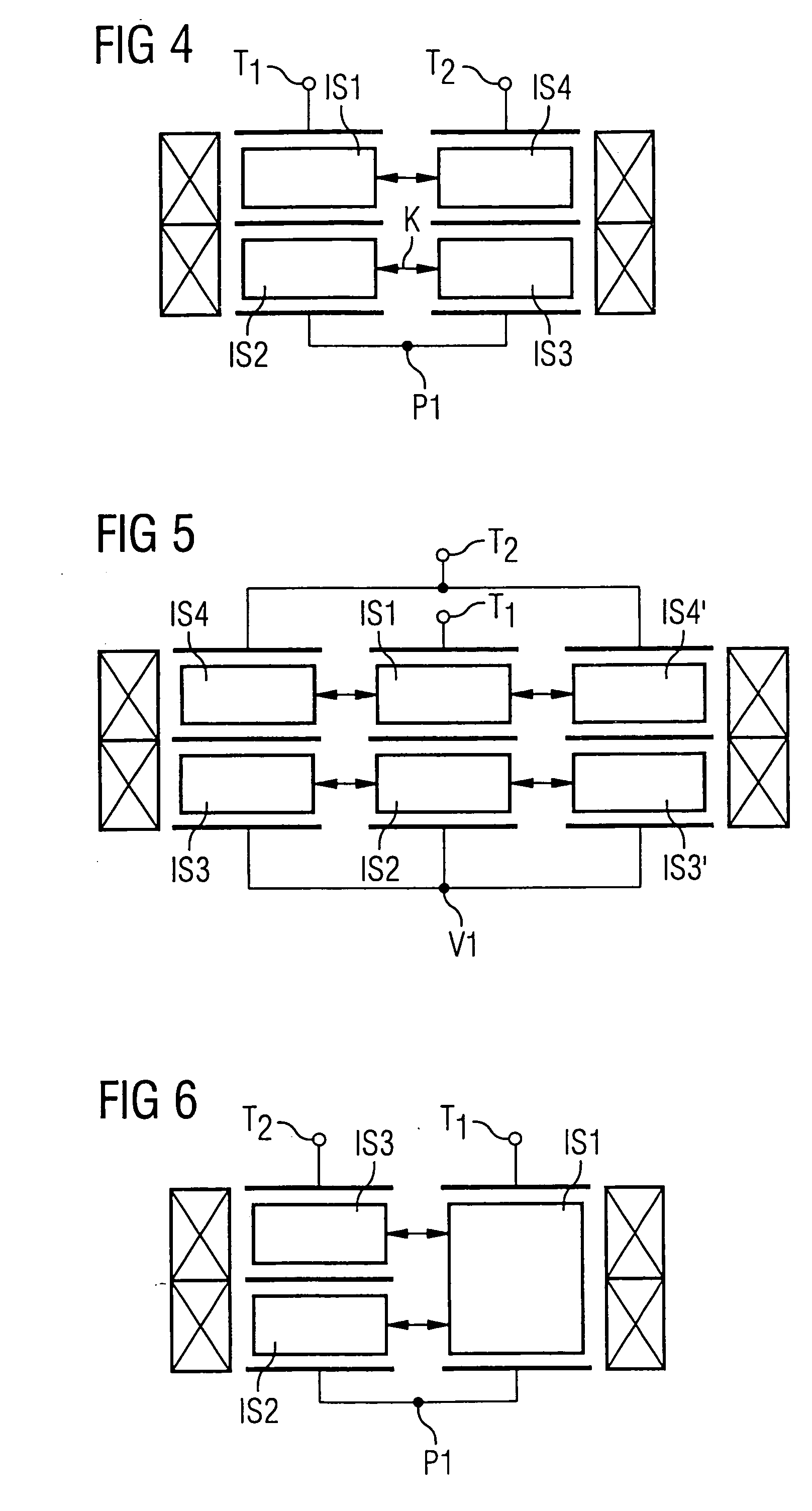
[0020] With the invention, deviation is made from the strictly regular ladder-type structure known from U.S. Pat. No. 5,486,800 and the symmetry is deliberately disturbed in order to achieve further advantageous effects. While the known ladder-type structure obeyed a wave parameter design, an inventive component is based on an effective parameter design. It allows a completely novel filter structure that, in addition to many new characteristics, is primarily also characterized by a smaller space requirement (chip surface). In all exemplary embodiments, at least the regular branching of parallel branches and the requirement of the respective interdigital transducers designed identically in the serial or parallel branch are omitted. A filter behavior can therewith be designed that possesses arbitrarily many pole locations, thus shows gating behavior at arbitrary frequencies and overall exhibits an improved insertion attenuation. It results from the latter that only little energy is lost in the signal path due to the acoustic coupling of the interdigital transducers, since the acoustic energy escaping from an individual interdigital transducer can be re-coupled into the system at another location.
[0021] Due to the at least partial omission of the reflectors between acoustically coupled interdigital transducers, the often excessive power density at the transition between reflector and interdigital transducer is reduced.
[0022] Via the acoustic coupling, the acoustic length of the interdigital transducer is increased, and thereby edge effects are reduced, likewise the ripple connected with this.
[0023] In acoustically coupled interdigital transducers, the adjacent (coupled) interdigital transducer acts as a reflector. The reflector losses are thereby omitted; at the same time, the space necessary for the component is reduced.
[0024] By coupling acoustically various interdigital transducers not arranged in the same branch, the degree of necessary cascading is reduced in the filter; at the same time, a minimal number of electrode fingers and an optimally small aperture can be maintained.
[0025] Via the acoustic coupling, the excitation of counter-phase signals in an interdigital transducer is achieved, whereupon the stopband suppression and / or the insulation is increased in critical frequency ranges.

Problems solved by technology

Further known filters are also two-port resonators that, however, can only seldom be used in the RF range due to their narrowband transmission characteristics.

Method used


Image

  • Filter comprising acoustically coupled resonators
  • Filter comprising acoustically coupled resonators
  • Filter comprising acoustically coupled resonators

Examples


Embodiment Construction

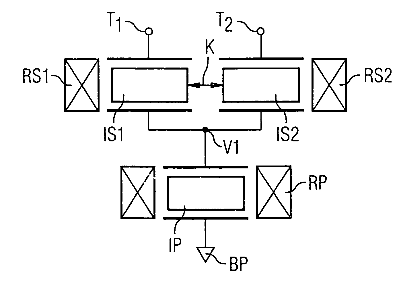
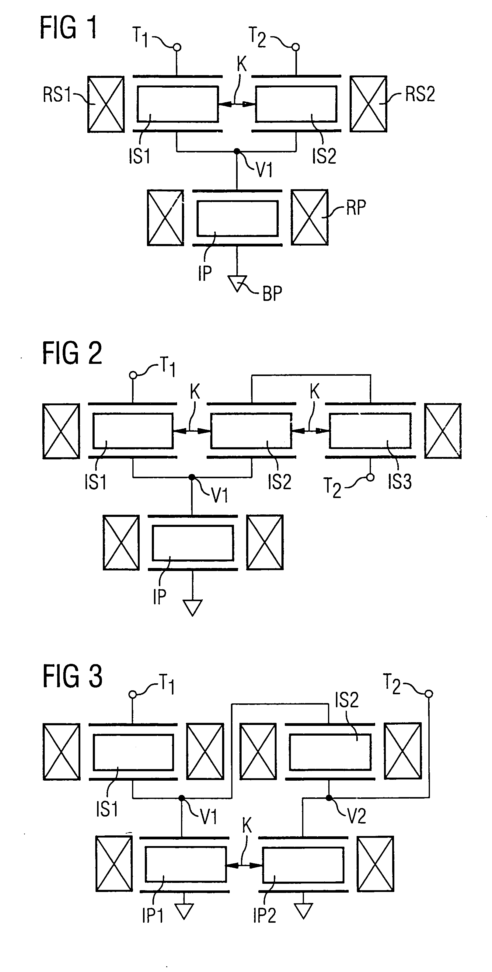
[0095]FIG. 1 shows a first inventive component operating with surface-proximal acoustic waves in which a first serial interdigital transducer IS1 and a second serial interdigital transducer IS2 are connected in series between a first connection T1 and a second electrical connection T2. Both of the interdigital transducers are arranged in-line consecutively in the propagation direction and close to one another, so that they can acoustically couple with one another, as indicated by the double-arrow K. The acoustic track with the serial interdigital transducers IS1, IS2 is bordered on both sides by one reflector RS1, RS2 per side. A parallel interdigital transducer IP that is bordered on both sides by one reflector RP per side is arranged between a branching point V1 that is placed in the circuit between both serial interdigital transducers IS1 and IS2 and a reference potential BP. A one port resonator is fashioned in the parallel branch while both serial interdigital transducers with ...


PUM


Abstract

A component operating with surface-proximal acoustic waves, in particular a filter with novel structure, has interdigital transducers arranged in serial and parallel branches, which are acoustically coupled with one another in different configurations. The component provides a loss-poor filter with simultaneously space-saving arrangement of the filter elements.

Description

BACKGROUND OF THE INVENTION [0001] The invention concerns a component working with surface-proximal acoustic waves, in particular a filter with a network structure, in which component resonators are embedded. [0002] Today, SAW, or surface acoustical wave, filters are predominantly used as bandpass filters in the RF range in the front end of end apparatuses of mobile communication, for example in mobile telephones. These are significantly fashioned as reactance or DMS filters. [0003] Circuits of DMS filters with reactance elements are also known, in particular with one-port resonators executed in SAW technology. Thus, for example, a DMS filter is known from DE 198 18 038 A in which two DMS filters circuited in serial or in parallel are circuited in series with reactance elements on the input or output side. Moreover, it is proposed there to arrange both DMS filters inside an acoustic track and two adjacent DMS filters are to be divided via intermediate reflectors. [0004] Further know...

Claims


Application Information

Patent Timeline
Patent Type & Authority Applications(United States)
IPC IPC(8): H03H9/00H03H9/02H03H9/145H03H9/25H03H9/64
CPCH03H9/0042H03H9/02716H03H9/02748H03H9/02779H03H9/6453H03H9/14588H03H9/14591H03H9/6433H03H9/645H03H9/02795
Inventor BAUER, THOMASHASHIMOTO, KEN-YAROESLER, ULRIKERUILE, WERNERMEISTER, VEITKUHRAU, HEIDEJAKOB, MICHAEL
Owner SNAPTRACK
Learn More